
Page 356 - Divyank Tyagi
P. 356
322 | ChAPter 8 AdvAnced Modeling And MAssing
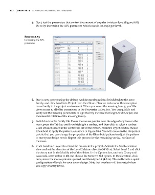
5. Next, test the parameters that control the amount of angular twist per level (Figure 8.83).
Do so by increasing the APL parameter (which stands for angle per level).
Figure 8.83
increasing the APl
parameter
6. Start a new project using the default Architectural template. Switch back to the mass
family, and click Load Into Project from the ribbon. Place an instance of the conceptual
mass family in the project environment. When you select the massing family, you’ll be
given access to all of its parameters in the Properties dialog box. You can quickly and
easily test the massing parameters to significantly increase the height, width, taper, and
incremental rotation of the massing family.
7. Switch back to the family file. Hover the mouse pointer near the edge of any face on the
mass, press the Tab key until you highlight a surface, and then click to select a surface.
Click Divide Surface in the contextual tab of the ribbon. From the Type Selector, choose
Rhomboid to apply the pattern, as shown in Figure 8.84. You will notice in the Properties
palette that you can change the properties of the Rhomboid pattern to adjust the pattern
to meet your design needs. Repeat this process for the remaining vertical surfaces of
the mass.
8. Click Load Into Project to reload the mass into the project. Activate the South elevation
view and set the elevation of the Level 2 datum object to 30’ (9 m). Select Level 2 and click
the Array tool in the Modify tab of the ribbon. In the Options bar, uncheck Group and
Associate, set Number to 60, and choose the Move To 2nd option. In the elevation, click
once, move the mouse pointer upward, and then type 15’ (4.5 m). This will create a quick
configuration of levels for your tower design. Note that no plans will be created when
you copy or array levels.
c08.indd 322 05-05-2014 16:48:00