
Page 441 - House of Maxell
P. 441
MORE COMPLICATED ELEMENTS OF FEED LINES 421
8.4.4 K - and J - Immittance Inverters
Looking back at Table 7.1 and 7.2 in Chapter 7 and Section 8.1 of this chapter, we see that a
plenty of different discontinuities and components in feed line can be used as building elements
of filters shown in Figure 8.4.1. One of such coaxial filter realization was demonstrated in
Figure 7.3.4. According to this drawing, we have used two different types of discontinuities,
one series and another shunt, that might seriously complicate filter implementation. It is
preferable to have either all shunt or all series elements. Sometimes, such straight filter
implementation is prohibited by extremely high impedance variations from element to element
that makes their practical realization questionable or just impossible. The effective way to go
around is to use so-called K- or J-inverters [8, 10] depicted in Figure 8.4.4 at some central
frequency .
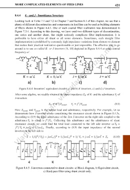
′
Figure 8.4.4 Inventors’ equivalent circuits: a) and b) K-invertors, c) and d) J-invertors.
After some algebra, we readily obtained the input impedance of K- and the admittance of
J-invertors
2
2
= / , = / (8.9)
Here and is the output load and admittance, respectively. For example, let us
demonstrate how J-inverter works considering the resonance circuit shown in Figure 8.4.5a.
According to (8.9) the input admittance of the first J-invertor on the right side coupled to the
admittance is equal to / . Collecting this admittance and the admittances of shunt
2
0
0
resonance circuit, we could find the total load connected to the left side invertor as =
Σ
/ + + 1 ℒ . Finally, according to (8.9) the input impedance of the second
2
⁄
0
1
1
invertor on the left side is
= 1/( / ) = + 1 ℒ + 1 = ℒ ̂ + 1 ̂ + (8.10)
2
2
2
⁄
⁄
⁄
⁄
Σ 1 1 0 0
Figure 8.4.5 J-invertors connected to shunt circuits: a) Block diagram, b) Equivalent circuit,
c) Band-pass filter using shunt circuit only.