
Page 453 - House of Maxell
P. 453
MORE COMPLICATED ELEMENTS OF FEED LINES 433
As an example here, let us illustrate the optical filter applications in so-called Fiber-To-The-
Home (FTTH) or Fiber-To-The-Promises (FTTP) network that should deliver simultaneously
the upstream and downstream ultra-fast (today up to 10 Gbps) the Internet, phone and digital
video directly to any locality like residence and business buildings, hotels and hospitals,
stadiums, etc. Connecting all these sites directly to fiber optic cable enables enormous
30
improvements in the bandwidth that can be provided to consumers. Figure 8.4.14b
demonstrates the block diagram of such fiber connectivity using three infrared signals with
central wavelengths 1310 nm, 1490 nm and 1550 nm corresponding to the frequencies 228.849
THz, 201.203 THz and 193.414 THz, respectively. If so, the frequency gaps between two
adjacent frequencies are 27.646 THz and 7.789 THz and there enough space for group signals
with ±5 THz bandwidth. Meanwhile, just at the lowest frequency, the bandwidth of 10 THz is
only 5.18%. Therefore, the critical part of such systems is the narrow banded optical filters
called typically dichroic mirrors, whose can add or drop signals of a particular wavelength in
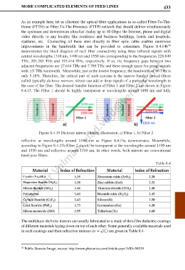
the core of the fiber. The desired transfer function of Filter 1 and Filter 2 are shown in Figure
8.4.15. The Filter 1 should be highly transparent at wavelengths around 1490 nm and fully
Figure 8.4.15 Dichroic mirror filtering illustration: a) Filter 1, b) Filter 2
reflective at wavelengths around 1550 nm as Figure 8.4.15a demonstrates. Meanwhile,
according to Figure 8.4.15b Filter 2 should be transparent at the wavelengths around 1490 nm
and 1550 nm and reflective around 1310 nm. In other words, both mirrors are conventional
band-pass filters.
Table 8.4
The multilayer dichroic mirrors are usually fabricated as a stack of thin-film dielectric coatings
of different materials laying down on top of each other. Some generally available materials used
in such coatings and their refractive indexes ( = √ ) are given in Table 8.4.
30 Public Domain Image, source: http://www.photonics.com/Article.aspx?AID=50539