
Page 88 - MUD-catalog-2019_Neat
P. 88
DF 88
20/14 DF DF Quick-Change DH-Style
Frame & Companion Insert Molds
Standard Solid: Standard Laminated:
2.00 3.00 1 6.0 x 6.0 6.0 x 6.0
2.00 3.00 1 1 1 1 1
6.000
6.000
Ejector
9.750 6.000 Ejector .562 .562 6.000 Ejector .562 .562
Ejector
5.50 5.50 Half Half 5.50 5.50 Half Half
9.750
19.50 STANDARD SOLID
INSERT MOLD .687 .687 .562 ±.001 .687 .687 .562 ±.001
.562 ±.001
.562 ±.001
5.996
5.996
Offset
Offset
19.50 Offset 5.996 Offset 5.996
6.456
6.456
6.456
6.456
8.375 .307 .307 .230 .230 .307 .307 .230 .230 1.00 1.00
A A A A A2 A2
8.375 Ø .500 Ø .500
Ø .500
Ø .500
MUD Quick-Change Mold Frames and Inserts for Double H-Style | 20/14 DF
OFFSET 5.437
5.187 B B B B 1.00 1.00
6.937 B2 B2
3.750
3.750
OFFSET 13.88 5.437 3.750 2 2 3.750 2 2
5.25
Ejection
5.187 2 3.50 STANDARD LAMINATED Ejection .360 .360 Ejection .360 .360
Ejection
3/8 x 5° 6.937 13.88 INSERT MOLD 3 3 3 3
Lead .360 .360 5.00 5.00 .360 .360 5.00 5.00
Central
Central
5.25 2 3.50 Central Central
3/8 x 5°
5.25 .12
Lead
3.75
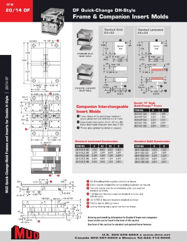
Double “H” Style
5.25 .12 Companion Interchangeable Quick-Change™ Frame
3.75
Insert Molds ITEM NO. A B
3.937 .937 20/14 DF 322 1.877 1.877
1 Frame clamps at this end of insert mold and 20/14 DF 323 2.377 1.877
3.937 .937 ejector plates are flush with this end of insert. 20/14 DF 324 2.377 2.377
3 2 Support post not supplied. Grind +.001 to +.002 20/14 DF 325 2.877 2.377
higher than height of ejection (see page C 131). 20/14 DF 326 2.877 2.877
3 Thicker plate optional (quotation on request).
3
1.874
5.62 6.000
R Ø 0
1.874
5.62 6.000 Standard Laminated Construction Standard Solid Construction
R Ø 0
ITEM NO. A A2 B2 B ITEM NO. A B
20/14 SLD 282 1.877 0.877 0.877 1.877 20/14 SSD 222 1.877 1.877
20/14 SLD 283 2.377 1.377 0.877 1.877 20/14 SSD 223 2.377 1.877
20/14 SLD 284 2.377 1.377 1.377 2.377 20/14 SSD 224 2.377 2.377
20/14 SLD 285 2.877 1.877 1.377 2.377 20/14 SSD 225 2.877 2.377
20/14 SLD 286 2.877 1.877 1.877 2.877 20/14 SSD 226 2.877 2.877
4 5
4 5
Ø S ± .001
.218 Ø 2.0 7 .500 1.12 1 3/4-10 handling holes supplied standard as shown.
2 Ejector system designed for spring loading (quotation on request).
.50 Ø S ± .001
.218 Ø 2.0 7 .500 1.12 A 3 Cutout in ejector plate to accommodate pillar post supplied
.50 +.002 standard as shown.
.50 6.000 –.000 UC 3816 4 1 1/8 diameter knockouts supplied standard at center and
Ø 1.25 A 3.50 off center.
3/8-16 THD
.50 +.002 RUNNER .248 UC 3816 5 1/2-13 THD at knockout locations standard as shown.
–.000
Ø 1.25 6.000 .312 B 6 Positive ejector plate guidance.
RUNNER .248 3/8-16 THD 7 Locking locating ring supplied standard as shown.
.36 ± .0005
.312 3.750 B
5.06
.81 6.18
1.31
±
.36 1.12 .0005 1.12
3.750
.81 .50 .12 1.12 .187 1.31 5.06 6.18 Ordering and installing information for Double H frame and companion
insert molds can be found in the front of this section.
2.38 6
1.12 See front of this section for standard and optional frame features.
.50 .12 .187
2.38 6
U.S. 800-626-6653 n www.dme.net
Canada 800-387-6600 n Mexico 52-442-713-5666