Page 41 - Hot Runner & Control Systems 2020
P. 41

Hot One Nozzles                                         29     39
                                          Housing, Nozzle Plate and

                                   Gate Machining Dimensions Detail

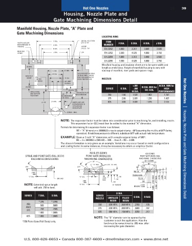
            Manifold Housing, Nozzle Plate, “A” Plate and
            Gate Machining Dimensions                                                     Ø4.000 LOCATING RING BORE  Ø2.756 0.000   HEAD BORE
                                                                                                                      +0.001
                                                                  LOCATING RING
                                                                                                                         Ø2.125 HEATER BORE
                                   F  DIA.           .261 DIA.  HOLE THRU  ITEM
            WATER LINES ARE                          5/16–18  TAP            F DIA.  G DIA.  H DIA.  J DIA.               Ø8.00  DWL
            RECOMMENDED IN         G  DIA.                         NUMBER                   BUSHING HEATER               (OPTIONAL FOR
            HOUSING                                  .34 DEEP                               CABLE EXIT                   ANTI-ROTATION)
                                   H  DIA.           2-PLC'S.  TYP.  EHL0252  4.000  3.312   3.000   2.500
            RISER PAD              J  DIA.           .219                              0.75
            HEIGHT                                                  EHL0253  5.500   4.625   4.000   3.750              1.174
                                                                    EHL0254  4.000   3.312   3.000   2.500
                                                                    EHL0255  5.500   4.625   4.000   3.750                (4) 5/16-18 UNC
                                                                  Manifold housing and insulator sheet are to be same width and
                  .250 MIN.                                       length as mold base. Height of manifold housing to vary with    1.174
                                                                                                        3.50
                                   K  DIA.  .25  MIN.             stackup of manifold, riser pads and spacer rings.  1.378
                                  M  DIA.         HOUSING MUST BE EQUAL                                                 Ø8 X18LG DWL
                 MANIFOLD                         TO RISER PADS,  SPACER                                                (OPTIONAL FOR
                  HEIGHT  1.000            N  DIA.  RING AND MANIFOLD AT  NOZZLES        NOTE:  MATCH MACHINE           ANTI-ROTATION)
                       (1.500  FOR                ROOM TEMPERATURE                          NOZZLE TIP ORIFICE   R 0.750
                       625  SERIES)       .625  WIRE                                  6                                  INSULATION SHEET
                                          CHANNEL                                     4                  Ø0.625          (OPTIONAL)
                                                                                      +.001           N DIA. MIN for
                                                                                      5
                 .250 MIN.                                                                 N DIA. MIN for
                                                +.001                SERIES   K DIA.  –.000               HIGH           1.743
                                            .250 MIN.  –.000                                 SQ. COIL
                    SPACER RING                  1.875 NOZZLE PLATE                  M DIA.           PERFORMANCE
                    AND SUPPORT         .250     RECOMMENDED          250      1.56   1.501    1.062      1.187
                    PAD HEIGHT          RECOMMENDED
                                                                                      2
                                        (.125  MIN.)                  375      2.06   2.001    1.250      1.437
                            A + BE  .31 MIN.   WATER LINES ARE        625      3.06   3.001    1.875  R0.030  2.125
                                               RECOMMENDED IN
                                               "A" PLATE AND                                MIN. WIRE CHANNEL  0.375    2.125  0.06  X 45˚  0.06  X 45˚  0.06  X 45˚   0.633 Min. - 1.283 Max.
                                               NOZZLE PLATE                                                          MIN.  0.469 -0.001 HEAD C’BORE
                                           .125 RAD.   MAX.                           3                                  0.000
                                                                                      1                                        A + BE
                                        NOTE:  The expansion factor must be taken into consideration prior to machining for, and installing, nozzle.
                                                                                           WATER LINES
                                              This expansion factor (BE) must then be added to the nominal “A” dimension.  0.31  MIN.  1"-16 UN
                                                                                                                      TORQUE TO 30 FT/LBS
                                        Formula  for determining this expansion factor is as follows:
                                                   BE = “A” dimension x .00000633 x nozzle setpoint temp – 68°(assuming the mold is at 68˚F during
                                                  operation). If mold temperature is different, substitute 68˚F with actual mold temperature.
                                        EXAMPLE:  Given a 3 inch “A” dimension, with a nozzle setpoint temp. of 500°:
                                                  BE = 3 x .0000063 x (500-68) = .008… thus A + BE = 3.008.           Custom Hot Runner Systems   |    New Products
                                        The above information is only given as an example. Variations may occur based on mold configurations
                                        and cooling factor. In some instances, it may be necessary to obtain an empirical factor.
                                                          250 & 375 SERIES                    625 SERIES
 GATE-MATE  4    SPRUE AND POINT GATE (FULL BODY)       POINT GATE (BODILESS)             POINT GATE (BODILESS)
 MACHINING  DIMENSIONS  MACHINING DIMENSIONS           MACHINING  DIMENSIONS              MACHINING  DIMENSIONS
 +.0005                                                     80°                              Ø2.125 MIN              Ø2.125 MIN            Ø2.125 MIN             Ø2.125 MIN
  –.0000                                                    “R”  RAD.  .010 –.015  RAD.        80°
 30°0'  .7500  DIA.  30°0'                        30°0'                                 30°                                          30°
                                                                                                              30°                                          30°
 90°                                                                                  R0.125
 .375  RAD.  80°  .770  +.0005                                                                                         +.0005        CUSTOMER    +.0005  25°  MAX.
                      –.0000
                   “S” DIA.                         “0”  DIA.     .005       .180     R0.010-0.015     0.125  0.235   ØS -.0000   MIN.  RADIUS TO  ØS -.0000  0.08 MIN.  +.0005  0.08 MIN.
                                                                                                                                                                    -.0000
                                     .080 LAND                    LAND                   R0.312              0.47                    SUIT                          ØS
 .187  SPH.  RAD.  .030                              +.0005       MAX.     .100                       AT TANG.
 “0'  DIA.  .005  LAND (MAX. )                        –.0000             .020               ØO     0.005 LAND MAX             0.08
                 NOTE:  Extended sprue length       “Q” DIA.             AT  TANGENT      +0.0005
                       will add .750 to land.                                         Ø0.6250 0.0000  0.020
                                                                           O DIA.
                 SERIES   T DIA.  S DIA.                      SERIES
                                                              NOZZLE  UNFILLED   FILLED   Q DIA.  R RAD.
                                                                                                                      Hot One Nozzles   |    Housing, Nozzle Plate and Gate Machining Dimensions Detail
                          *.375   *.3755                               RESIN   RESIN
                  250     .500     .5005                        250   .028 MIN.  .060 MIN.  .3750  .125
                  AND                                           375   .028 MIN.  .060 MIN.  .5000  .187
                  375     .750     .7505
                          1.000   1.0005                        625   .080 MIN.  .100 MIN.  .6250  .312
                  625     1.000   1.0005
                                                             NOTE:  The “O” diameter can be opened by the
               *250 Point Gate (Full Body) only.                   customer to suit the application. Also the
                                                                   land must be remachined to .005 max. after
                                                                   increasing the gate diameter.
                U.S. 800-626-6653  n Canada 800-387-6600  n dme@milacron.com  n www.dme.net
   36   37   38   39   40   41   42   43   44   45   46