
Page 172 - Corkjoint E-Catalogue
P. 172
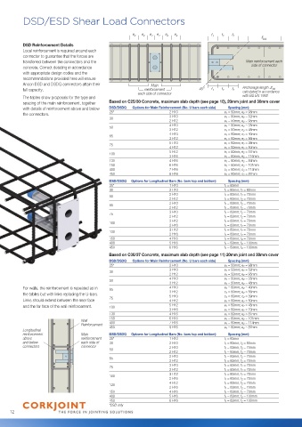
DSD/ESD Shear Load Connectors
e 2 e 2 e 1 e 1 e 2 e 2 f 1 f 2 f 2
bd
DSD Reinforcement Details
Local reinforcement is required around each
connector to guarantee that the forces are
transferred between the connectors and the Main reinforcement each
concrete. Correct detailing in accordance side of connector
with appropriate design codes and the
recommendations provided here will ensure
Ancon DSD and DSDQ connectors attain their Main
full capacity. reinforcement 45° f 1 f 2 f 2 Anchorage length bd
each side of connector calculated in accordance
The tables show proposals for the type and with BS EN 1992
spacing of the main reinforcement, together Based on C25/30 Concrete, maximum slab depth (see page 10), 20mm joint and 30mm cover
with details of reinforcement above and below DSD/DSDQ Options for Main Reinforcement (No. U bars each side) Spacing (mm)
the connectors. 25* 2 H10 e 1 = 50mm; e 2 = 98mm
30 3 H10 e 1 = 50mm; e 2 = 52mm
2 H12 e 1 = 50mm; e 2 = 95mm
4 H10 e 1 = 50mm; e 2 = 35mm
50
3 H12 e 1 = 50mm; e 2 = 48mm
4 H10 e 1 = 60mm; e 2 = 40mm
65
3 H12 e 1 = 60mm; e 2 = 56mm
5 H10 e 1 = 60mm; e 2 = 39mm
75
4 H12 e 1 = 60mm; e 2 = 50mm
5 H12 e 1 = 60mm; e 2 = 57mm
100
3 H16 e 1 = 60mm; e 2 = 116mm
130 4 H16 e 1 = 60mm; e 2 = 84mm
150 6 H16 e 1 = 60mm; e 2 = 101mm
400 7 H16 e 1 = 60mm; e 2 = 114mm
450 9 H16 e 1 = 60mm; e 2 = 87mm
DSD/DSDQ Options for Longitudinal Bars (No. bars top and bottom) Spacing (mm)
25* 1 H10 f 1 = 60mm
30 2 H10 f 1 = 60mm; f 2 = 60mm
2 H10 f 1 = 60mm; f 2 = 70mm
50
2 H12 f 1 = 60mm; f 2 = 70mm
2 H10 f 1 = 60mm; f 2 = 70mm
65
2 H12 f 1 = 60mm; f 2 = 70mm
3 H10 f 1 = 60mm; f 2 = 70mm
75
2 H12 f 1 = 60mm; f 2 = 70mm
3 H12 f 1 = 60mm; f 2 = 70mm
100
2 H16 f 1 = 60mm; f 2 = 70mm
3 H12 f 1 = 60mm; f 2 = 70mm
130
2 H16 f 1 = 60mm; f 2 = 70mm
150 4 H16 f 1 = 60mm; f 2 = 70mm
400 5 H16 f 1 = 60mm; f 2 = 100mm
450 6 H16 f 1 = 60mm; f 2 = 100mm
Based on C30/37 Concrete, maximum slab depth (see page 11) 20mm joint and 30mm cover
DSD/DSDQ Options for Main Reinforcement (No. U bars each side) Spacing (mm)
25* 2 H10 e 1 = 50mm; e 2 = 98mm
3 H10 e 1 = 50mm; e 2 = 52mm
30
2 H12 e 1 = 50mm; e 2 = 95mm
4 H10 e 1 = 50mm; e 2 = 35mm
50
3 H12 e 1 = 50mm; e 2 = 48mm
For walls, the reinforcement is repeated as in 65 4 H10 e 1 = 60mm; e 2 = 40mm
the tables but with links replacing the U-bars. 3 H12 e 1 = 60mm; e 2 = 56mm
e 1 = 60mm; e 2 = 39mm
5 H10
Links should extend between the near face 75 4 H12 e 1 = 60mm; e 2 = 50mm
and the far face of the wall reinforcement. 100 5 H12 e 1 = 60mm; e 2 = 45mm
3 H16 e 1 = 60mm; e 2 = 70mm
130 4 H16 e 1 = 60mm; e 2 = 81mm
150 6 H16 e 1 = 60mm; e 2 = 101mm
Wall 400 7 H16 e 1 = 60mm; e 2 = 114mm
Reinforcement 450 9 H16 e 1 = 60mm; e 2 = 87mm
Longitudinal
reinforcement Main DSD/DSDQ Options for Longitudinal Bars (No. bars top and bottom) Spacing (mm)
above reinforcement 25* 1 H10 f 1 = 60mm
and below each side of 30 2 H10 f 1 = 60mm; f 2 = 60mm
connectors connector 2 H10 f 1 = 60mm; f 2 = 70mm
50
2 H12 f 1 = 60mm; f 2 = 70mm
2 H10 f 1 = 60mm; f 2 = 70mm
65
2 H12 f 1 = 60mm; f 2 = 70mm
3 H10 f 1 = 60mm; f 2 = 70mm
75
2 H12 f 1 = 60mm; f 2 = 70mm
3 H12 f 1 = 60mm; f 2 = 70mm
100
2 H16 f 1 = 60mm; f 2 = 70mm
4 H12 f 1 = 60mm; f 2 = 70mm
130
2 H16 f 1 = 60mm; f 2 = 70mm
150 4 H16 f 1 = 60mm; f 2 = 70mm
400 5 H16 f 1 = 60mm; f 2 = 100mm
450 6 H16 f 1 = 60mm; f 2 = 100mm
*DSD only
12