
Page 63 - Parker - Hydraulic and Lube Filtration Products
P. 63
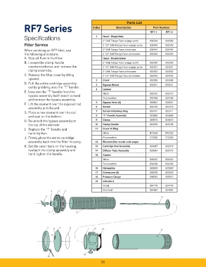
Parts List
               RF7 Series                               Index         Description         RF7-1     RF7-2
                                                                                            Part Number

               Specifi cations                             1   Head - Single Inlet
                                                              2” SAE Flange Face w/gage ports  932549  932549
               Filter Service                                 2 1/2” SAE Flange Face w/gage ports  932483  932483
               When servicing an RF7 fi lter, use              2” SAE Flange Face w/indicator  932484  932484
               the following procedure:                       2 1/2” SAE Flange Face w/indicator  932485  932485
               A. Stop all fl ow to the fi lter.                Head - Double Inlets
               B. Loosen the clamp handle                     2” SAE Flange Face w/gage ports  932550  932550
                  counterclockwise and  remove the            2 1/2” SAE Flange Face w/gage ports  932551  932551
                  clamp assembly.                             2” SAE Flange Face w/indicator  932552  932552
               C. Remove the fi lter cover by lifting          2 1/2” SAE Flange Face w/indicator  932553  932553
                  upward.
                                                          2   Cover                       932288   932288
               D. Pull the entire cartridge assembly
                                                          3   Bypass Mount                932521   932521
                  out by grabbing onto the “T” handle.
                                                          4   Lipseal
               E. Unscrew the “T” handle from the
                                                              Nitrile                     932415   932415
                  bypass assembly (with mesh screen)
                                                              Fluorocarbon                932488   932488
                  and remove the bypass assembly.
                                                          5   Bypass Valve (6)            930507   930507
               F.  Lift the element over the exposed rod
                                                          6   Screen                      932416   932416
                  assembly and discard.
                                                          7   Screen Retaining Ring       932417   932417
               G. Place a new element over the rod
                  and seat on the bottom.                 8   “T” Handle Assembly         903889   903889
               H. Re-attach the bypass assembly to        9   Clamp                       909876   909876
                  the top of the element.                 10  Clamp Handle                926768   926768
               I.  Replace the “T” handle and             11  Cover O-Ring
                  hand-tighten.                               Nitrile                     N72263   N72263
               J.  Firmly place the entire cartridge          Flourocarbon                V72263   V72263
                  assembly back into the fi lter housing.  12  Element (See model code page)
               K. Set the cover back on the housing,      13  Cartridge Rod Assembly      933067   932418
                  reattach the clamp assembly and         14  Diffuser Tube Assembly      933064   932419
                  hand tighten the handle.                15  Gasket
                                                              Nitrile                     932420   932420
                                                              Fluorocarbon                932489   932489
                                                          16  Nameplate                   920928   920928
                                                          17  Drivescrew (2)              900028   900028
                                                          18  Pressure Gauge              936912   936912
                                                          19  Indicators
                                                              Visual                      924776   924776
                               3    6   5                     Electrical                  924964   924964
                            8                                                                    13


                              7               12
                                4


                             9      2     11
                                17                   1   19   15                                14
                               16


                                                   18
                             10
                                                             58