
Page 64 - Parker - Hydraulic and Lube Filtration Products
P. 64
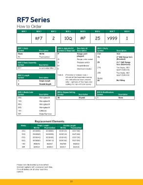
RF7 Series


               How to Order

                    BOX  1      BOX  2       BOX  3      BOX  4       BOX 5       BOX  6       BOX  7       BOX  8

                               RF7            2         10Q           MP          25         Y999            1


                BOX 1: Seals                      BOX 5: Indicator(s)  (See Note A)  BOX 7: Ports
                Symbol            Description     Symbol (2 Required)  Description  Symbol           Description
                 None              Nitrile        P                Gauge, port      Inlet            Side
                                                                   plugged
                 F3                Fluorocarbon                                     Y9               2” SAE fl ange face
                                                  G                Gauge, color coded                (Standard)
                BOX 2: Basic Assembly             S                Pressure switch  Z9               2½” SAE fl ange
                Symbol            Description     M                Visual indicator                  face (Standard)
                 RF7               In-tank return fi lter                           2Y9              Two Inlets, 180°
                                                  E                Electrical indicator              apart (Optional)
                                                                                    2Z9              Two Inlets, 180°
                BOX 3: Length                     Note A:   (First letter of indicator code =        apart (Optional)
                Symbol            Description            left side of fi lter head when looking   Outlet
                                                         into inlet with bowl down; second
                 1                 Single length                                    99               No fi tting
                                                         letter = right side of fi lter head when
                 2                 Double length         looking into inlet with bowl down.)


                BOX 4: Media Code                 BOX 6: Bypass Setting             BOX 8: Modifi cations
                Symbol            Description     Symbol            Description     Symbol            Description
                 20Q               Microglass III  25               25 psid         1                 None
                 10Q               Microglass III
                 05Q               Microglass III
                 02Q               Microglass III
                 10C               Cellulose
                 WR                Water Removal

                               Replacement Elements

                   Media         Single Length         Double Length
                              Nitrile  Fluorocarbon  Nitrile  Fluorocarbon
                    20Q      933800Q    933808Q     933812Q    933156Q
                    10Q      933802Q    933809Q     933814Q    933155Q
                    05Q      933804Q    933810Q     933816Q    933153Q
                    02Q      933806Q    933811Q     933818Q    933152Q
                    10C       908648     923551     932498      932503
                    WR        928563     933853     932501      932506


               Please note the bolded options refl ect
               standard options with a reduced lead-time.
               Consult factory on all other lead-time
               options.


                                                             59