Page 235 - Schroeder - Hydraulic And Lube Filtration
P. 235

Top-Ported Return Line Filter MLF1


                            Type Fluid  Appropriate Schroeder Media                            Fluid                 IRF
                                                            ®
                  Petroleum Based Fluids  All E media (cellulose), Z-Media and ASP media (synthetic)  Compatibility  TF1
                                              ®
                    High Water Content  All Z-Media  (synthetic)
                       Invert Emulsions  10 and 25 µ Z-Media  (synthetic)                                           KF3
                                                     ®
                         Water Glycols    3, 5, 10 and 25 µ Z-Media  (synthetic)
                                                        ®
                                              ®
                       Phosphate Esters    All Z-Media  (synthetic) with H (EPR) seal designation and 3 and 10 µ E    KL3
                                      media (cellulose) with H (EPR) seal designation and all ASP media (synthetic)
                             Skydrol ®    3, 5, 10 and 25 µ Z-Media  (synthetic) with H.5 seal designation and
                                                        ®
                                      W media (water removal) with H.5 seal designation (EPR seals and stainless    LF1–2"
                                      steel wire mesh in element, and light oil coating on housing exterior) and    Skydrol  is a registered
                                                                                                     ®
                                      all ASP media (synthetic).                               trademark of Solutia Inc.  MLF1
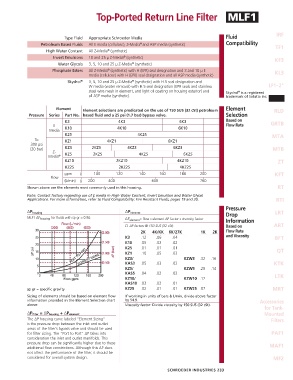
                         Element    Element selections are predicated on the use of 150 SUS (32 cSt) petroleum   Element  RLD
             Pressure  Series  Part No.  based fluid and a 25 psi (1.7 bar) bypass valve.      Selection
                            K3                     4K3                      6K3                Based on           GRTB
                       E                                                                       Flow Rate
                      Media  K10                  4K10                      6K10
                            K25                            4K25                                                    MTA
                To          KZ1               4KZ1                     6KZ1
              300 psi
              (20 bar)      KZ3        2KZ3           4KZ3               6KZ3                                      MTB
                       Z-
                     Media ®  KZ5       2KZ5               4KZ5               6KZ5
                            KZ10                  2KZ10                    4KZ10                                     ZT
                            KZ25                   2KZ25                    4KZ25
                            gpm   0     100       120      140      160     180      200                            KFT
                      Flow
                            (L/min)  0  200   400               600                  760
            Shown above are the elements most commonly used in this housing.                                         RT
            Note: Contact factory regarding use of E media in High Water Content, Invert Emulsion and Water Glycol
            Applications. For more information, refer to Fluid Compatibility: Fire Resistant Fluids, pages 19 and 20.  RTI
                                                                                               Pressure
            ∆P housing                               ∆P element                                Drop                 LRT
            MLF1 ∆P housing  for fluids with sp gr = 0.86:  ∆P element =  flow x element ∆P factor x viscosity factor  Information
                                                     El. ∆P factors @ 150 SUS (32 cSt):        Based on            ART
                                                            2K   4K/KK  6K/27K       1K   2K   Flow Rate
                                                     K3     .12   .06    .04                   and Viscosity        BFT
                                                     K10    .05   .02    .02
                                                     K25    .01   .01    .01                                         QT
                                                     KZ1    .10   .05    .03
                                                     KZ3/                     KZW3   .32  .16
                                                     KAS3   .05   .03    .02                                       KTK
                                                     KZ5/                     KZW5   .28  .14
                                                     KAS5   .04   .02    .02
                                                     KZ10/                    KZW10 .12                             LTK
                                                     KAS10 .03    .02    .01
            sp gr = specific gravity                 KZ25   .02   .01    .01  KZW25 .07                            MRT
            Sizing of elements should be based on element flow   If working in units of bars & L/min, divide above factor
            information provided in the Element Selection chart   by 54.9.                                    Accessories
            above.                                   Viscosity factor: Divide viscosity by 150 SUS (32 cSt).
                                                                                                                for Tank-
            ∆P filter  = ∆P housing  + ∆P element                                                              Mounted
            The ∆P housing curve labeled “Element Sizing”                                                         Filters
            is the pressure drop between the inlet and outlet
            areas of the filter’s bypass valve and should be used
            for filter sizing. The “Port to Port” ∆P takes into                                                   PAF1
            consideration the inlet and outlet manifolds. This
            pressure drop can be significantly higher due to these                                                MAF1
            additional flow constrictions. Although this ∆P does
            not affect the performance of the filter, it should be
            considered for overall system design.                                                                  MF2


                                                                       SCHROEDER INDUSTRIES  233
   230   231   232   233   234   235   236   237   238   239   240