
Page 27 - Schroeder - Hydraulic And Lube Filtration
P. 27
Ordering Information
For each filter that is shown in Sections 3, 4, 5 , 6, 7 (partial) and 8 there is a Model Number Selection Model Number
Chart. This chart lists all the configurations and accessories available for that specific filter. Selection
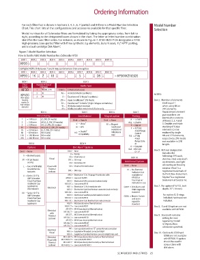
Model numbers for all Schroeder filters are formulated by listing the appropriate codes, from left to
right, according to the designated boxes shown in the chart. The letter or letter/number combination
identifies the basic filter series. For instance, as shown in Figure 7, KF30-3KZ3-P-D5 designates a KF30
high-pressure, base-ported filter with three synthetic 3 µ elements, Buna N seals, 1 ⁄ 2 " NPTF porting,
1
and a visual cartridge Dirt Alarm. ®
Figure 7. Model Number Selection
How to Build a Valid Model Number for a Schroeder KF30:
BOX 1 BOX 2 BOX 3 BOX 4 BOX 5 BOX 6 BOX 7 BOX 8 BOX 9 BOX 10
KF30 – – – – – – – – –
Example: NOTE: Only boxes 7 and 9 may contain more than one option
BOX 1 BOX 2 BOX 3 BOX 4 BOX 5 BOX 6 BOX 7 BOX 8 BOX 9 BOX 10
KF30 – 1K – Z – 10 – – – S – – D5 – = KF301KZ10SD5
BOX 1 BOX 2 BOX 3
Filter Number & Size of
Series Elements Media Type
KF30 1 K, KK, 27K Omit = E Media (Cellulose)
2 K AS = Anti-Stat Media (synthetic) NOTES:
KFN30 ® ®
(Non-bypass 3 K Z = Excellement Z-Media (synthetic)
®
housings ZW = Aqua-Excellement ZW Media Box 2. Number of elements
requires Zx ZX = Excellement Z-Media (High Collapse centertube) must equal 1
®
®
high collapse
elements) W = W Media (water removal) when using KK or
M = Media (reusable metal mesh) N size only 27K elements.
BOX 4 BOX 5 BOX 6 BOX 7 Replacement element
MIcron Rating Seal Material Magnet option Porting part numbers are
1 = 1 Micron (Z, ZW, ZX media) Omit = Buna N Omit = None P = 1 ⁄2" NPTF identical to contents
1
of Boxes 2, 3, 4 and
3 = 3 Micron (AS,E, Z, ZW, ZX media) ® P32 = 2" NPTF 5. Double and triple
5 = 5 Micron (AS, Z, ZW, ZX media) V = Viton M = Magnet S = SAE-24
10 = 10 Micron (AS,E,M, Z, ZW, ZX media) H = EPR inserts (not F = 1 ⁄2" SAE stacking of K-size
1
25 = 25 Micron (E, Z, ZW, ZX media) = Skydrol ® available w/ 4-bolt flange elements can be
60 = 60 Micron (M media) H.5 indicator in Code 61 replaced by single
150 = 150 Micron (M media) compatibility cap) F32 = 2" SAE KK and 27K elements,
260 = 260 Micron (M media) 4-bolt respectively. ZW media
flange Code not available in 27K
BOX 8 BOX 9 61 length.
®
Options Dirt Alarm Options O = Subplate
B24 = ISO 228 Box 5. H.5 seal designation
Omit = None Omit = None G-1 ⁄2" includes the
1
D = Pointer
X = Blocked bypass D5 = Visual pop-up BOX 10 following: EPR seals,
50 = 50 psi bypass Visual D5C = D5 in cap stainless steel wire mesh
setting D9 = All stainless D5 Additional Options on elements, and light
L = Two ⁄4" NPTF inlet Visual with D8 = Visual w/ thermal lockout Omit = None oil coating on housing
1
®
& outlet female Thermal D8C = D8 in cap N = No-Element exterior. Viton is a
test ports Lockout Indicator (not registered trademark of
U = Series 1215 ⁄16 MS5 = Electrical w/ 12 in. 18 gauge 4-conductor cable available w/ DuPont Dow Elastomers.
7
®
UNF Schroeder MS5LC = Low current MS5 KFN30 or Skydrol is a registered
Check Test Point MS10 = Electrical w/ DIN connector (male end only) housings w/ trade mark of Solutia Inc.
installed in Cap MS10LC = Low current MS10 indicator in cap
(upstream & MS11 = Electrical w/ 12 ft. 4-conductor wire G509 = Dirt Alarm and Box 7. For options F & F32, bolt
downstream) Electrical MS12 = Electrical w/ 5 pin Brad Harrison connector (male end only) drain opposite depth .75" (19 mm).
UU = Series 1215 ⁄16 MS12LC = Low current MS12 standard
7
UNF Schroeder MS16 = Electrical w/ weather-packed sealed connector G588 = Electric Switch For option O, O-rings
Check Test Point MS16LC = Low current MS16 and drain included; hardware not
installed in Cap MS17LC = Electrical w/ 4 pin Brad Harrison male connector opposite included.
(upstream) MS5T = MS5 (see above) w/ thermal lockout standard
MS5LCT = Low current MS5T Box 8. X and 50 options are not
MS10T = MS10 (see above) w/ thermal lockout available with KFN30.
Electrical MS10LCT = Low current MS10T
with
MS12T = MS12 (see above) w/ thermal lockout
Thermal MS12LCT = Low current MS12T Box 9. Standard indicator
Lockout setting for non-
MS16T = MS16 (see above) w/ thermal lockout bypassing model
MS16LCT = Low current MS16T is 50 psi unless
MS17LCT = Low current MS17T otherwise specified.
1
MS = Cam operated switch w/ ⁄2" conduit female connection
Electrical MS13 = Supplied w/ threaded connector & light
Visual Box 10. Options N, G509 and
MS14 = Supplied w/ 5 pin Brad Harrison connector & light (male end)
Electrical MS13DCT = MS13 (see above), direct current, w/ thermal lockout G588 are not available
Visual with MS13DCLCT = Low current MS13DCT with KFN30. N option
Thermal MS14DCT = MS14 (see above), direct current, w/ thermal lockout should be used in
Lockout MS14DCLCT = Low current MS14DCT conjunction with
dirt alarm.
SCHROEDER INDUSTRIES 25