
Page 28 - Schroeder - Hydraulic And Lube Filtration
P. 28
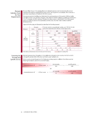
Element    For each filter shown in the catalog, there is an element selection chart to determine the correct
                Selection Chart  element to be used for a particular flow requirement (see Figure 8 for an example). The chart uses a
                                 petroleum-based hydraulic fluid with 150 SUS viscosity.
                      for Flow
                 Requirements    The process involves the following: Determine the working pressure of the system (3000 psi in this
                                 example) and the maximum flow (75 gpm). Then select the media (Z-Media ), and the micron filtration
                                                                                      ®
                                 (3 µ). For example, the filter selected, following the above steps, is a KF30-2KZ3-P-D5. If the system
                                 pressure is 5000 psi and all other parameters are the same, then the model number would be
                                 KF50-2KZ3-P-D5.
                                 Figure 8. KF30 Housing and Element Selection Chart for Flow Requirement

                                                Element     Element selections are predicated  on the use of 150 SUS (32 cSt)
                                 Pressure   Series   Part No.  petroleum based fluid and a 40 psi (2.8 bar) bypass valve.
                                                    K3          1K3           2K3         3K3       See MFK50
                                              E
                                            Media   K10            1K10          2K10    3K10   3K10    See MFK50
                                                    K25                    1K25                      2K25
                                   To               KZ1              1KZ1                 2KZ1          3KZ1
                                 3000 psi
                                 (210 bar)          KZ3                 1KZ3                     2KZ3    3KZ3
                                              Z     KZ5                    1KZ5                  2KZ5     3KZ5
                                            Media
                                                    KZ10                     1KZ10                  2KZ10  3K10
                                                    KZ25                        2KZ25                    2KZ25
                                                    gpm         0                       25                    50                     75                    100                    125              150
                                             Flow
                                                    (L/min)     0                       100                   200                      300                    400                   500         600
                                 Shown above are the elements most commonly used in this housing.                    requires 2" porting (P32)

                 Correcting for   Element pressure drop information in this publication is based on the viscosity (150 SUS or 32cSt)
                  Viscosity and   and specific gravity (0.86) of the most commonly used hydraulic oils.
               Specific Gravity  If the viscosity or specific gravity of the fluid you are designing for is different from these, use the
                                 following formulas to obtain the correct ΔP values.

                                                                          SUS viscosity        specific gravity
                                  Corrected element ΔP  = ΔP from curve  x               x
                                                                             150                   0.86
                                                                      OR

                                                                          cST viscosity        specific gravity
                                  Corrected element ΔP  = ΔP from curve  x               x
                                                                             32                    0.86


                              26   SCHROEDER INDUSTRIES