Page 361 - Schroeder - Hydraulic And Lube Filtration
P. 361

Filter Dirt Alarm  Selection                        Appendix A
                                                                        ®


            Schroeder-designed dirt alarms provide a vital measure of protection to your system by indicating the appropriate time for element replacement. For
            your convenience, this Appendix has been organized to help you determine which Schroeder Dirt Alarm will be most suitable for your application.
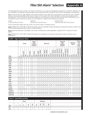
            Step 1: Review the charts on pages 359-361 which have been devised to show which alarms are available for a particular filter. Chart 1 addresses
            indicators for Schroeder high pressure filters found in Section 3 of this catalog. Chart 2 shows HydraSpin and medium pressure filters found in
            Sections 4 and 5. Charts 3 and 4 show the indicators available for tank-mounted, return line, and medium pressure filters of Sections 4, 5, 6 and 7.
            To facilitate the process of selecting an indicator, we have classified our indicators into the following six categories:
            • Visual                       • Electrical                      • Electrical Visual
            • Visual with Thermal Lockout   • Electrical with Thermal Lockout   •  Electrical Visual with Thermal Lockout
            These six classifications appear at the top of each of the charts to assist in the selection process.
            Step 2: APPLIES ONLY TO ELECTRICAL INDICATORS. Narrow down the possibilities of electrical indicators by reviewing the contents of Charts 5 and
            6, which identify voltages and current ranges for electrical indicators.
            Step 3: Review the descriptions, photographs, part numbers and specifications (where applicable) on pages 362-367 to verify your dirt alarm
            selection.
            Step 4: APPLIES ONLY TO ELECTRICAL INDICATORS. Review the cross reference of old electrical indicator part numbers to the new ones on
            pages 368-371.

             CHART 1 High Pressure Filters
                                              Visual                                Electrical               Electrical
                                               with                                   with         Electrical   Visual
                                 Visual                        Electrical                                     with
                                             Thermal                                 Thermal        Visual   Thermal
                                             Lockout                                 Lockout                 Lockout


                                  D5C (in cap)  D9C (in cap)  D8C (in cap)  MS5 / MS5LC  MS10 / MS10LC  MS12 / MS12LC  MS16 / MS16LC  MS17LC  MS18 / MS18LC  MS19 / MS19LC  MS10T / MS10LCT  MS12T / MS12LCT  MS16T / MS16LCT  MS17LCT  MS18T / MS18LCT  MS19T / MS19LCT  MS13DCT/MS13DCLCT  MS14DCT/MS14DCLCT


             Filter         D  D5    D5R  D9  D8    D8R      MS11    MS17                          MS  MS2  MS13  MS14
             NF30                                                                     
             NFS30                                                                    
             YF30                                                                        
             DF40                                                                      
             PF40                                                                       
             CF40                                                                      
             RF60                                                                        
             RFS50                                                                            
             CF60                                                                        
             VF60                                                                        
             KF30                                                                    
             TF50                                                                    
             KF50                                                                    
             KC50                                                                    
             KC65                                                                   
             KFH50                                                                   
             MKF50                                                                 
             FOF60-03                                                                    
             NOF30-05                                                                         
             NOF50-760                                                                   

              Chart 2  HydraSPIN and RLD

                                Visual                   Electrical

             Filter     L     R   B      VA    VM   M     DTC  DTO   DW
             GH                                             
             RLD                                                   

                                                                       SCHROEDER INDUSTRIES  359
   356   357   358   359   360   361   362   363   364   365   366