
Page 365 - Schroeder - Hydraulic And Lube Filtration
P. 365
Filter Dirt Alarm Selection: Step 3 Appendix A
®
In addition to providing an electrical signal to provide a desired action, Schroeder electrical visual indicators also Electrical Visual
provide a visual indication of when an element needs to be changed. In the case of the MS and MS2 switches,
the visual indicator is a color-coded disk, whereas the MS13 and MS14 dirt alarms provide a light.
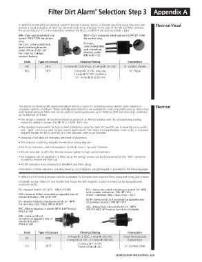
MS—Cam operated electrical MS2—Cam operated electrical switch P/N LF-1540
switch P/N LF-376 for switch for switch only.
only.
For cam, color-coded disk, For cam,
and mounting bracket, color-coded disk,
order P/N A-LF-831-1#. and mounting
For internal linkage, bracket, order
contact factory. P/N A-NF-132.
Code Type of Contact Electrical Rating Connection
MS SPDT 15 Amps @ 125/250 vac, 0.5 Amp @ 125 VDC 1 ⁄2" conduit, female
MS2 SPDT 3 Amps @ 12 VDC inductive, 10" Pigtail
3 Amps @ 12 VDC resistance,
10.1 Amps @ 125/250 VAC
The electrical indicators (MS Series) provide an electrical signal for activating various electric alarm systems or Electrical
complete machine shutdown. These cartridge-style indicators are available on most Schroeder pressure, return line,
and medium pressure filters and can be used for working pressures up to 5000 psi (345 bar) and cyclic conditions
up to 4000 psi (276 bar).
• The design is modular; all electrical indicators consist of an MS10 indicator with the corresponding mating
connector added to convert the MS10 to a MS5, MS11 etc.
• The standard micro switch for high current indicators is good for both AC and DC use. A separate micro switch
with “gold” contacts is used for low current applications. This means that specification of AC or DC is no longer
required (except for MS13 and MS14) in the indicator code or part number.
• Housings of all electrical indicators are made of aluminum.
• The indicator model tag includes the electrical wiring diagram.
• All of our indicators, with the exception of MS16, have a “ground” terminal.
• We are now able to offer the thermal lockout option to high current indicators.
• All indicators can be installed in a filter cap as the wiring harness can be disconnected at the “DIN” connector
in order to remove the filter cap.
• All MS indicators have achieved the NEMA4X and IP65 ratings.
Information on these indicators, including drawing, circuit diagram, and photograph is provided on the following pages.
A different set of electrical pressure switches is available for Schroeder tank-mounted filters, along with heavy duty versions.
Schroeder suction filters (ST and models that house the SKB magnetic suction strainer) can be equipped with
a vacuum switch.
VS—Vacuum Switch ( ⁄8" NPT) P/N A-LFT-305 ES1—Heavy duty electrical pressure switch ( ⁄8" NPT)
1
1
with conduit connection P/N LFT-1010
VSR—Same as VS but mounted on opposite side of (Black = common; Red = N.O.; Blue = N.C.)
standard location P/N A-LFT-305
ES1R—Same as ES1 but mounted on opposite side
ES—Standard electrical pressure switch ( ⁄8" NPT) of standard location P/N LFT-1010
1
for tank-mounted filters P/N A-LF-927
VS1—Heavy Duty Vacuum Switch ( ⁄8" NPT)
1
ESC—Electrical pressure switch (MTA & MTB only) P/N LFT-1107, LF Pressure Switch for McNeilus
P/N A-LF-927
ESR—Same as ES but
mounted on opposite side of
standard location
P/N A-LF-927
Code Type of Contact Electrical Rating Connection
8 Amps @ 12 VDC, 1 Amp @ 120 VAC Screw Terminal with
ES SPST
4 Amps @ 24 VDC, 0.5 Amp @ 240 VAC Rubber Boot
10 Amps @ 115 VAC
ES1 SPDT 50mA-5A @ 24 VDC 1 ⁄2" Conduit, Male
SCHROEDER INDUSTRIES 363