
Page 15 - Parker - AC30 Variable speed drive
P. 15
AC30 Variable Speed Drive
Technical Specifications
Connections
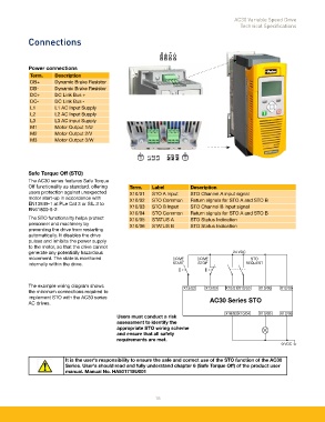
DB+ DB- DC+ DC-
Power connections
Term. Description
DB+ Dynamic Brake Resistor
DB- Dynamic Brake Resistor
DC+ DC Link Bus +
DC- DC Link Bus -
L1 L1 AC Input Supply
L2 L2 AC Input Supply
L3 L3 AC input Supply
M1 Motor Output 1/U
M2 Motor Output 2/V
M3 Motor Output 3/W
L1 L2 L3 M1 M2 M3
Safe Torque Off (STO)
The AC30 series features Safe Torque
Off functionality as standard, offering Term. Label Description
users protection against unexpected X10/01 STO A Input STO Channel A input signal
motor start-up in accordance with X10/02 STO Common Return signals for STO A and STO B
EN13849-1 at PLe Cat 3 or SIL 3 to X10/03 STO B Input STO Channel B input signal
EN61800-5-2.
X10/04 STO Common Return signals for STO A and STO B
The STO functionality helps protect X10/05 STATUS A STO Status Indication
personnel and machinery by X10/06 STATUS B STO Status Indication
preventing the drive from restarting
automatically. It disables the drive
pulses and inhibits the power supply
to the motor, so that the drive cannot
generate any potentially hazardous 24 VDC
movement. The state is monitored DRIVE DRIVE STO
internally within the drive. START STOP REQUEST
The example wiring diagram shows X13/02 X13/03 X10/01 X10/03 X10/06 X12/05
the minimum connections required to
implement STO with the AC30 series AC30 Series STO
AC drives.
X10/02 X10/04 X10/05 X12/06
Users must conduct a risk
assessment to identify the
appropriate STO wiring scheme
and ensure that all safety
requirements are met.
0 VDC
It is the user's responsibility to ensure the safe and correct use of the STO function of the AC30
Series. User's should read and fully understand chapter 6 (Safe Torque Off) of the product user
manual. Manual No. HA501718U001
15