Page 21 - Parker - AC30 Variable speed drive
P. 21

AC30 Variable Speed Drive
                                                                                           Accessories and Options

            Input and Output Cards


            7004-03-00 - Real Time Clock and Motor Thermistor Input Module
            Motor Temperature Sensing       1 motor thermistor input
            Thermistor Compatibility        PTC, NTC, KTY
            Thermistor Resistance Range     0 - 4.5 kΩ
            Time Format                     Seconds
            Accuracy (drive powered)        ±1 minute / month (RTC trim=0)
            Accuracy (drive unpowered)      ±5 minutes / month (RTC trim=0)
            Battery Backup Duration         6 Months
            Description:
            A real-time clock (RTC) is provided for the user to program the drive to perform
            functions at specified times. The RTC has battery backup, so it continues to run
            when the drive is unpowered. The battery recharges when the drive is powered.
            An isolated motor thermistor input is also included in the 7004-03-00 module.


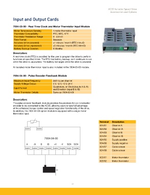
            7004-04-00 - Pulse Encoder Feedback Module
            Maximum Input Frequency         250 Hz per channel
            Supply Voltage Output           5 V, 12 V, 15 V, 24 V
                                            Quadrature, or Clock (inputs A & /A)
            Input Format
                                            and Direction (input B & /B)
            Motor Thermistor Details        Same as 7004-02-00


            Description:
            The pulse encoder feedback module provides the provision for an incremental
            encoder to be connected to the AC30, allowing users to take full advantage
            of the enhanced torque control and speed regulation functionality of the drive.
            In addition, the 7004-04-00 option module is equipped with a single motor
            thermistor input.


                                                                                  Terminal   Description
                                                                                  X24/01     Channel A
                                                                                  X24/02     Channel /A
                                                                                  X24/03     Channel B
                                                                                  X24/04     Channel /B
                                                                                  X24/05     Supply positive
                                                                                  X24/06     Supply negative
                                                                                  X24/07     Cable screen
                                                                                  X24/08     Cable screen

                                                                                  X22/01     Motor thermistor
                                                                                  X22/02     Motor thermistor


                                                            21
   16   17   18   19   20   21   22   23   24   25   26