Page 102 - Wago_AutomationTechnology_Volume3_2015_US.pdf
P. 102

750-837

   3    PLC - CANopen Programmable Fieldbus Controller, MCS

  100   16-bit CPU


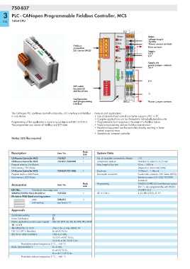
                                                                          CANopen   01  02    Status
                                                                           STOP   A           voltage supply
                                                                                    C         -System
                                                                           RUN   B   D        -Power jumper contacts
                                               Fieldbus                                       Data contacts
                                                                           TX
                                               connection                  OVERFLOW   24V  0V
                                               231 Series (MCS)            RX                 Supply
                                                                                              24 V
                                                                                              0 V
                                                                           I/O
                                                                                 +  +
                                                                           USR
                                                                                              Supply via
                                                                                              power jumper contacts
                                                                                              24 V
                                                                            W  750-837  —  —

                                               DIP switch            ON                       0 V
                                               for node ID        1 2 3 4 5 6 7 8
                                               and baud rate

                                               Configuration
                                               and programming                                Power jumper contacts
                                               interface


        The CANopen PLC combines control functionality, I/O interface and fieldbus   Features and applications:
        in one device.                                      • Use of decentralized control can better support a PLC or PC
                                                            • Complex applications can be divided into individually testable units
        Programming of the application is done in accordance with IEC 61131-3.   • Programmable fault response in the event of a fieldbus failure
        The programmer can access all fieldbus and I/O data.   • Signal pre-processing reduces fieldbus transmissions
                                                            • Peripheral equipment can be controlled directly, resulting in faster
                                                              system response times
                                                            • Stand-alone, compact controller
        Notice: EDS files required


        Description                  Item No.        Pack.    System Data
                                                     Unit
        CANopen Controller MCS       750-837         1        No. of controllers connected to Master  110
        CANopen Controller MCS       750-837/020-000  1       Transmission medium      Shielded Cu cable 3 x 0.25 mm²
        Program memory 256 Kbytes;                            Max. length of bus line  30 m ... 1000 m
        Data memory 192 Kbytes                                                         (depends on baud rate/cable)
        CANopen Controller MCS       750-837/021-000  1       Baud rate                10 Kbaud ... 1 Mbaud
        Program memory 640 Kbytes;                            Buscoupler connection    5-pole male connector, 231 Series (MCS),
        Data memory 832 Kbytes                                                         female connector 231-305/ 010-000
                                                                                       (included)
        Accessories                  Item No.        Pack.    Programming              WAGO-I/O-PRO 32, from firmware version
                                                     Unit                              SW 11, also programmable with WAGO-
        EDS files    Download: www.wago.com                                            I/O-PRO V2.3
        WAGO-I/O-PRO V2.3, RS-232 kit  759-333       1        IEC 61131-3              IL, LD, FBD (CFC), ST, FC
        Miniature WSB Quick marking system
                     plain           248-501         5
                     with marking    see Section 11

        Approvals
        Conformity marking        1
        Korea Certification
        Marine applications (versions upon request)  ABS, BV, DNV, GL, KR, LR, NKK, PRS, RINA
        r UL 508
        r ANSI/ISA 12.12.01       Class I, Div. 2, Grp. ABCD, T4
        TÜV 12.1297 X (Brasilien)  Ex nA IIC T4 Gc
        4 TÜV 07 ATEX 554086 X    I M2 Ex d I Mb,
                                  II 3 G Ex nA IIC T4 Gc,
                                  II 3 D Ex tc IIIC T135°C Dc
              Permissible ambient temperature 0 °C ... +60 °C
        IECEx TUN 09.0001 X       Ex d I Mb,
                                  Ex nA IIC T4 Gc,
                                  Ex tc IIIC T135°C Dc
              Permissible ambient temperature 0 °C ... +60 °C
   97   98   99   100   101   102   103   104   105   106   107