
Page 250 - Wago_AutomationTechnology_Volume3_2015_US.pdf
P. 250
750-523
4 1-Channel Relay Output Module 230 V AC, 16 A
248 Isolated output; 1 make contact; bistable; manual operation
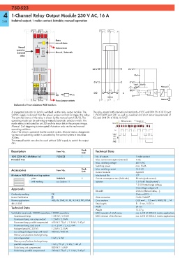
Status
HAND manual Mode
Manual 1 AUTO Data contacts
operation
Switched Manual / Automatic
status 0 HAND
24 V 24 V
10nF
0 V 0 V
DO DO L L 10nF 10nF
Manual
1 2 3 4 DO
L DO L
DO N L
750-523 750-523
Manual
Power jumper contacts
Delivered without miniature WSB markers
A connected actuator or load is switched via the relay output module. The The relay meets both international standards of IEC and DIN EN 61810 part
24VDC supply is derived from the power jumper contacts to trigger the relays. 1 /VDE 0435 part 201 as well as overload and short circuit requirements of
The switched status of the relay is shown by the manual switch (1/0). The IEC and DIN EN 61036 /61037.
operating mode can be set using a manual/automatic selector switch. The Manual operation Automatic reset
mode status is indicated by an LED and via status bits in the process image. Manual
Manual: Coil triggering is interrupted. Actuation only via the red manual 1 0
operating switches.
DO
Auto: The relay is operated via the control system. Manual status changeover
via manual operating switch is canceled by the control system in less than Control
system
500ms. AUTO
HAND
The manual switch can also be used without 24V supply to switch the output Supply
voltage
ON.
Description Item No. Pack. Technical Data
Unit
1DO 230V AC 16A Relay 1a/ 750-523 1 No. of outputs 1 make contact
Potential Free Max. current consumption (internal) 5 mA
Max. switching voltage 440 V AC
Switching power max. 5 kVA
Accessories Item No. Pack. Max. switching current 16 A AC
Unit
Contact material
AgSnO2
Miniature WSB Quick marking system Mechanical life 10 6
plain 248-501 5 Current consumption max. (field side) 80 mAs (peak current)
with marking see Section 11 Isolation 1.5 kV eff. (field/system)*;
* 2.5 kV rated surge voltage;
Approvals Overvoltage category III
Bit width 2 bits in (Manual status, - );
Conformity marking 1 2 bits out (DO, - )
Korea Certification Wire connection CAGE CLAMP ®
Marine applications ABS, BV, DNV, GL, KR, LR, NKK, PRS, RINA Cross sections 0.08 mm² ... 2.5 mm² / AWG 28 ... 14
r UL 508 Strip lengths 8 ... 9 mm / 0.33 in
Technical Data Width 24 mm
Weight 123.7 g
Switchable lamp loads 100000 operations / 30000 operations EMC immunity of interference acc. to EN 61000-6-2, marine applications
Incandescent lamp 1.25 kW / 2.5 kW EMC emission of interference acc. to EN 61000-6-3, marine applications
Fluorescent lamp, not compensated 1.2 kW / 2.5 kW
Fluorescent lamp, parallel compensated 650 W / 70 μF / 1.3 kW / 140 μF
Fluorescent lamp, dual circuit 2 x 1.2 kW / 2 x 2.5 kW
Halogen lamp (AC 230 V) 1.2 kW / 2.5 kW
Low voltage halogen lamp with transf. 500 VA / 500 VA
Mercury arc/Sodium discharge lamp,
not compensated 1 kW / 2 kW
Mercury arc/Sodium discharge lamp,
parallel compensated 1 kW / 70 μF / 2 kW / 140 μF
Dulux lamp, not compensated 800 W / 1.6 kW
Dulux lamp, parallel compensated 560 W / 70 μF / 1.1 kW / 140 μF