
Page 321 - Wago_AutomationTechnology_Volume3_2015_US.pdf
P. 321
750-642
Radio Receiver Module 4
319
4.7
13 14
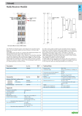
Function A C Antenna socket Antenna
RxD B Antenna socket
RSSI D SMA SMA
RxD
Data contacts
1 5 1 5
Logic
Radio
module
2 6 2 6
RSSI
Function
RSSI RxD
3 7 3 7
4 8 4 8
750-642 750-642
Delivered without miniature WSB markers
The 750-642 I/O Module receives radio telegrams from maintenance-free, Four billion code numbers provide for clear transmitter/receiver assignment.
battery-less and wireless switches and sensors based on EnOcean radio Repeated, time-shifted transmission of the radio telegrams, at very short trans-
technology. mission times, results in a high level of protection against external interference.
The module can be used with any controller of the WAGO-I/O-SYSTEM 750. The maximum transmission range is approx. 300 meters in open field.
Preprogrammed function blocks make integration easy. Depending on the building materials used and on the spatial geometry, the
The energy required for switch or sensor operation is produced by converting range may be reduced to typically 30 meters (see manual for more informati-
one type of energy (heat, solar or mechanical energy) into usable electrical on). The LED (RSSI) indicates a sufficient input level.
energy. The radiated energy from the transmitter modules is around one million *Documentation available in German and English.
times smaller than mobile phones. Almost any number of sensors is possible. An SMA socket which is integrated into the housing allows the connection of
However, the maximum number is around 100 transmitters per module, due to an external antenna. The 758-910 external antenna has a magnetic stand and
the increasing density of switches/sensors. a 2.5m long coax cable with SMA plug (available as an accessory).
Description Item No. Pack. Technical Data
Unit
Radio Receiver Module 750-642 1 Frequency band 868.3 MHz
Transmission range 300 m in open field (typ. in buildings see
manual)
Transmission protocol (radio telegram) EnOcean
Current consumption (internal) 80 mA
Power supply via system voltage DC/DC
Accessories Item No. Pack. Isolation 500 V antenna connection/system
Unit
1 x 24 bits in/out (3 bytes user data)
Internal bit width
Miniature WSB Quick marking system 1 x 8 bits control/status
plain 248-501 5 Dimensions (mm) W x H x L 24 x 64* x 100
with marking see Section 11 *+ excess length of the SMA socket
approx. 6.5 mm
External antenna GSM 900/1800 758-910 1 Weight 80 g
EMC immunity of interference acc. to EN 61000-6-2
Approvals EMC emission of interference acc. to EN 61000-6-3
Conformity marking RTTE www.wago.com
Conformity marking 1
Korea Certification
r UL 508
r ANSI/ISA 12.12.01 Class I, Div. 2, Grp. ABCD, T4
4 TÜV 07 ATEX 554086 X I M2 Ex d I Mb,
II 3 G Ex nA IIC T4 Gc,
II 3 D Ex tc IIIC T135°C Dc
Permissible ambient temperature 0 °C ... +60 °C
IECEx TUN 09.0001 X Ex d I Mb,
Ex nA IIC T4 Gc,
Ex tc IIIC T135°C Dc
Permissible ambient temperature 0 °C ... +60 °C