
Page 322 - Wago_AutomationTechnology_Volume3_2015_US.pdf
P. 322
753-646
4 KNX/EIB/TP1 Module
320
753-646 753-646
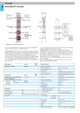
A: Router mode E: Device mode
13 14
B: KNX programming F: Buffer overflow
mode A E G: Internal error
C: Data transfer KBus B F H: KNX bus voltage
C G
D: Data transfer KNX D H
Connector
Data contacts
not 1 5
connected
Programming button
KNX
Connection of 2 6
Programming Programming programming Prog KNX bus
button button button voltage
Prog
RxD
3 7
+KNX bus +KNX bus + KNX bus +KNX
+KNX
Attention: TPUART TxD
BUS BUS Internal bridge in Logic
connector
4 8 A E
- KNX bus - KNX bus – KNX bus –KNX B F
–KNX C G
D H
Delivered without miniature WSB markers
The 753-646 KNX/EIB/TP1 I/O Module serves to connect a KNX/EIB/TP1 *1: See www.wago.com: Documentation; WAGO I/O System 753; Specialty
network. The module supports two different functions: Modules; KNX/EIB/TP1 Module; Device Mode
2. Router mode: When the 750-849 Series KNXnet/IP Controller is
1. Device mode: With this module, all programmable controllers (*1) that are connected to the first 753-646 Series KNX/EIB/TP1 Module, the device can
relevant for building automation can be connected to a KNX/TP1 network. In be operated as a KNXnet/IP router. The module is switched to router mode
a KNX network, the module appears as a standard KNX device and is linked automatically. An application program is not required for operation in router
using the ETS Professional commissioning tool. The module supports a mode. Additional modules that are connected to a KNXnet/IP controller are
maximum of 253 communication objects with any DPTs, 254 group addresses addressed in device mode by the application.
and 254 associations. The application is programmed using WAGO-I/O-PRO The 753 Series connector with internally bridged contacts (3/7 and 4/8) is
CAA. An ETS plugin, which is included in the WAGO product database, is part of the delivery.
required so that the data from the application program can be allocated to the Both an external KNX voltage supply and ETS Professional are required to
group addresses. operate the KNX/EIB/TP1 I/O module.
Description Item No. Pack. Technical Data
Unit
KNX/EIB/TP1 Module 753-646 1 KNX/TP1 bus specification 1.0
Voltage supply (KNX) via KNX power supply unit
Current consumption (KNX) 5 mA
Baud rate (KNX) 9.6 kbaud
Programming using WAGO-I/O-PRO CAA (device mode)
Commissioning (KNX side) with ETS plugin; programming button-bridge 2/6
Accessories Item No. Pack. Diagnostic information via FbKNX_Master_646 function block
Unit
(device mode)
WAGO ETS plug-in (included in WAGO see Section 1 Fault behavior via FbKNX_Master_646 function block
ETS product database) (device mode)
Miniature WSB Quick marking system Voltage supply (internal) via system voltage DC/DC
plain 248-501 5 Current consumption (internal) max. 25 mA
with marking see Section 11 Isolation 2.5 kV rms
Internal bit width 24 bytes
Programming button Bridge 2/6
Device mode:
Approvals Number of communication objects 253
Number of group addresses 254
KNX certified KNX Number of associations 254
Conformity marking 1 Supported DPTs All ( *acc. to KNX Specification
Korea Certification 03_07_02 Data Point Types V 1.0)
Marine applications ABS, BV, DNV, GL, KR, LR, NKK, PRS, RINA Router mode:
r UL 508 Can be used as -Line coupler yes
- Area coupler yes
- KNX interface yes
Wire connection CAGE CLAMP ®
Cross sections 0.08 mm² ... 2.5 mm² / AWG 28 ... 14
Strip lengths 9 ... 10 mm / 0.37 in
Width 12 mm
Weight 52.5 g
EMC immunity of interference acc. to EN 61000-6-2, marine applications
EMC emission of interference acc. to EN 61000-6-3, marine applications