
Page 412 - Wago_AutomationTechnology_Volume3_2015_US.pdf
P. 412
750-1515/040-000
750-1515/040-000
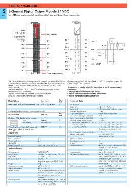
5 8-Channel Digital Output Module 24 VDC
410 for eXTReme environmental conditions; high-side switching, 2-wire connection
750-1515/ 750-1515/
040-000 040-000
13 14
1
2
Status 3
DO 1 ... DO 8 4
5 Data contacts
6
®
CAGE CLAMP S 7 8
connection DO 1 1 9 0 V
DO 1 1 9 0 V DO
2 10
DO 2 0 V
DO 2 0 V 270 pF
2 10
3 11
DO 3 0 V
DO 3 0 V
3 11 24 V DO
+ 24 V
4 12
DO 4 0 V 10 nF
DO 4 0 V
4 12 5 13 10 nF
DO 5 0 V
DO 5 5 13 0 V
0 V 0 V
6 14
DO 6 0 V 10 nF
DO 6 6 14 0 V
DO 7 7 15 0 V
DO 7 0 V
7 15 8 16
DO 8 0 V
DO 8 0 V
8 16
Power jumper contacts
This 2-wire digital output module provides 8 channels at a width of just 12 mm. An operating tool with a 2.5 mm blade (210-719) is required to open the
®
It transmits binary control signals from the automation device to the connected CAGE CLAMP S connections.
actuators (e.g., magnetic valves, contactors, transmitters, relays or other
electrical loads). The module is ideally suited for operation in harsh environmental
®
The module features CAGE CLAMP S connections providing push-in conditions:
termination of solid conductors. - strongly extended temperature range
A green LED indicates the switched status of each channel. - higher dielectric strength and EMC resistance
Field and system levels are electrically isolated. - higher vibration and shock resistance
Description Item No. Pack. Technical Data
Unit
8DO 24VDC 0.5A, 2-wire connection /XTR 750-1515/040-000 1 No. of outputs 8
Output type High-side switching
Type of load Inductive, resistive loads and lamps
Interference-free for use in safety functions (see manual) Max. switching frequency 1 kHz
Accessories Item No. Pack. Output current (max.) 0.5 A, short-circuit protected
Unit Max. current consumption (internal) 20 mA
Miniature WSB Quick marking system Current consumption typ. (field side) 15 mA
plain 248-501 5 Voltage via power jumper contacts 24 VDC
with marking see Section 11 under laboratory conditions +15 °C ... +35 °C 18 V ... 31.2 V (17.4 V ... 31.2 V) 1)
for -40 °C ... +55 °C 18 V ... 28.8 V (17.4 V ... 28.8 V) 1)
Operating tool, with partially insulated 210-719 50 for +55 °C ... +70 °C 18 V ... 26.4 V (17.4 V ... 26.4 V) 1)
shaft, type 1, blade (2.5 x 0.4) mm 1) including residual ripple of 15 %
Approvals Current via power jumper contacts (max.) 10 A
Isolation (peak value) 510 VAC or 775 VDC
Conformity marking 1 power supply/DIN rail
Korea Certification Rated surge voltage 1 kV
Marine applications GL Overvoltage category III
r UL 508 Bit width 8 bits
r ANSI/ISA 12.12.01 Class I, Div. 2, Grp. ABCD, T4 Vibration resistance acc. to IEC 60068-2-6 (acceleration: 5g),
Technical Data EN 60870-2-2, IEC 60721-3-1, -3,
EN 61131-2
®
Wire connection CAGE CLAMP S Shock resistance acc. to IEC 60068-2-27
Cross sections 0.25 mm² ... 1.5 mm² / AWG 24 ... 16 EMC immunity of interference acc. to EN 61000-6-1, -2, EN 61131-2,
Strip lengths 8 ... 9 mm / 0.33 in marine applications, EN 50121-3-2, -4, -5,
Dimensions (mm) W x H x L 12 x 62 x 100 EN 60255-26, EN 60870-2-1,
Height from upper-edge of DIN 35 rail EN 61850-3, IEC 61000-6-5, IEEE 1613,
Weight 48 g VDEW: 1994
Operating temperature -40 °C ... +70 °C EMC emission of interference acc. to EN 61000-6-3, -4, EN 61131-2,
Storage temperature -40 °C ... +85 °C EN 60255-26, marine applications,
Relative humidity 95 %, short-term condensation acc. to class EN 60870-2-1, EN 61850-3,
3K7 / IEC EN 60721-3-3 (except wind- EN 50121-3-2, -4, -5
driven precipitation, water and ice
formation)
Operating altitude without temperature derating: 0 m ... 2000 m;
with temperature derating: 2000 m ... 5000 m
(0.5 K/100 m); max.: 5000 m