
Page 417 - Wago_AutomationTechnology_Volume3_2015_US.pdf
P. 417
750-464/040-000
750-464/040-000
2-/4-Channel Analog Input Module for RTDs 5
for eXTReme environmental conditions 415
13 14
Function A E Function
B F
Error C G Error
D H
AI 1/AI 3 AI 2/AI 4
A1+ A2+
Data contacts
2-channel/ 2-channel/
+AI 1 2-wire 3-wire +AI 1 +AI 2 AI NTC A
+AI 2 MUX D Logic
A1- A2-
10 nF
−AI 1 -AI 1 -AI 2
−AI 2 Function
24 V Error
24 V
A3+ A4+
4-channel/ 10nF
+AI 3 2-wire +AI 3 +AI 4
+AI 4
0 V 0 V
A3- A4- 10nF
−AI 3 -AI 3 -AI 4 Common
−AI 4 (ground)
750-464/ 750-464/
040-000 Power jumper contacts 040-000
5
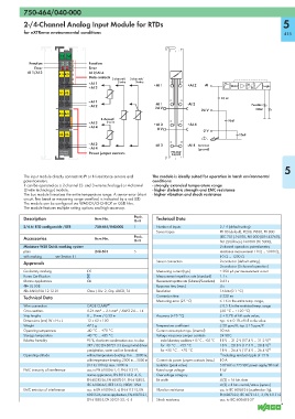
The input module directly connects to Pt or Ni resistance sensors and The module is ideally suited for operation in harsh environmental
potentiometers. conditions:
It can be operated as a 2-channel (2- and 3-wire technology) or 4-channel - strongly extended temperature range
(2-wire technology) module. - higher dielectric strength and EMC resistance
The bus module linearizes the entire temperature range. A sensor error (short - higher vibration and shock resistance
circuit, line break or measuring range overflow) is indicated by a red LED.
The module can be configured via WAGO-I/O-CHECK or GSD files.
The module features multiple setting options and high accuracy.
Description Item No. Pack. Technical Data
Unit
2/4 AI RTD configurable /XTR 750-464/040-000 1 Number of inputs 2 / 4 (default setting)
Sensor types Pt100 (default), Pt200, Pt500, Pt1000
Accessories Item No. Pack. (IEC 751), Ni100, Ni1000 (DIN 43760),
Unit Ni120 (Minco), Ni1000 (TK 5000),
Miniature WSB Quick marking system 2-channel operation: potentiometer,
plain 248-501 5 resistance measurement 10 Ω ... 5000 Ω,
with marking see Section 11 10 Ω ... 1200 Ω
Approvals Sensor connection 2-conductor (default setting),
3-conductor (2-channel operation)
Conformity marking 1 Measuring current (typ.) ≤ 350 μA per measurement circuit
Korea Certification Measurement repetition rate (standard) 1.1 s
Marine applications GL Measurement repetition rate (2-channel/2-conductor) 0.63 s
r UL 508 Response time (max.) 4 s
r ANSI/ISA 12.12.01 Class I, Div. 2, Grp. ABCD, T4 Resolution 16 bits (0.1 °C)
Technical Data Conversion time ≤ 320 ms
Measuring error (25 °C) ≤ 1 K in the entire temp. range,
Wire connection CAGE CLAMP ® ≤ 0.5 K in the restricted temp. range
Cross sections 0.25 mm² ... 2.5 mm² / AWG 24 ... 14 (-30 °C ... +120 °C)
Strip lengths 8 ... 9 mm / 0.33 in Accuracy (+25 °C) ≤ ± 0.2% of full scale value;
Dimensions (mm) W x H x L 12 x 62 x 100 typ.: ≤ ± 0.1% of full scale value
Weight 47.3 g Temperature coefficient ≤ 20 ppm/K; typ. ≤ 15 ppm/K
Operating temperature -40 °C ... +70 °C Current consumption typ. (internal) 50 mA
Storage temperature -40 °C ... +85 °C Voltage via power jumper contacts 24 VDC
Relative humidity 95 %, short-term condensation acc. to class under laboratory conditions +15 °C ... +35 °C 18 V ... 31.2 V (17.4 V ... 31.2 V) 1)
3K7 / IEC EN 60721-3-3 (except wind-driven for -40 °C ... +55 °C 18 V ... 28.8 V (17.4 V ... 28.8 V) 1)
precipitation, water and ice formation) for +55 °C ... +70 °C 18 V ... 26.4 V (17.4 V ... 26.4 V) 1)
Operating altitude without temperature derating: 0 m ... 2000 m; 1) including residual ripple of 15 %
with temperature derating: 2000 m ... 5000 m Current via power jumper contacts (max.) 10 A
(0.5 K/100 m); max.: 5000 m Isolation (peak value) 510 VAC or 775 VDC power supply/DIN rail
EMC immunity of interference acc. to EN 61000-6-1, -2, EN 61131-2, Rated surge voltage 1 kV
marine applications, EN 50121-3-2, -4, -5, Overvoltage category III
EN 60255-26, EN 60870-2-1, EN 61850-3, Bit width 4 (2) x 16 bits data
IEC 61000-6-5, IEEE 1613, VDEW: 1994 4 (2) x 8 bits control/status (option)
EMC emission of interference acc. to EN 61000-6-3, -4, EN 61131-2, EN Vibration resistance acc. to IEC 60068-2-6 (acceleration: 5g),
60255-26, marine applications, EN 60870-2-1, EN 60870-2-2, IEC 60721-3-1, -3, EN 61131-2
EN 61850-3, EN 50121-3-2, -4, -5 Shock resistance acc. to IEC 60068-2-27