
Page 419 - Wago_AutomationTechnology_Volume3_2015_US.pdf
P. 419
750-563/040-000
750-563/040-000
2-Channel Analog Output Module, 0/4 ... 20 mA / 6 ... 18 VDC 5
for eXTReme environmental conditions; 16-bit, configurable 417
13 14
Function AO 1 A E Function AO 2
B F
Error AO 1 C G Error AO 2
D H
A1+ A2– Data contacts
I
U
+AO 1 1 5 0...20mA A
+AO 2 + AO 1 + AO 2 AO 6...18V D Logic
S1+ S2+
Function Error
+ Sense AO 1 + Sense AO 1 2 6 + Sense AO 2 100 nF
+ Sense AO 2
+ 24 V +24 V
S1– S2–
− Sense AO 1 - Sense AO 1 3 7 - Sense AO 2
− Sense AO 2
0 V 0 V
M M
4 8
Common Common Common Common
(ground) 10 nF 10 nF
750-563/ (ground) 750-563/ (ground) (ground)
040-000 Power jumper contacts 040-000
5
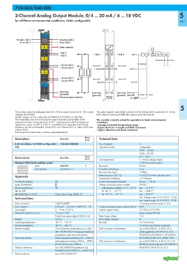
This analog output module generates 0/4–20 mA output currents or 6–18 V output The output signal is electrically isolated and transmitted with a resolution of 16 bits.
voltages for the field. Both internal system and field side supply power the module.
Output ranges can be configured via WAGO-I/O-CHECK or GSD files.
The module has two short-circuit-proof output channels and enables direct The module is ideally suited for operation in harsh environmental
connection of two 2-wire actuators to AO 1 and ground or AO2 and ground. conditions:
Signals are output via AO 1 or AO 2. In addition, the sense lines from 4-wire - strongly extended temperature range
actuators can be connected to -Sense AO1 and +Sense AO1 or -Sense AO2 and - higher dielectric strength and EMC resistance
+Sense AO2. - higher vibration and shock resistance
Both output channels have a common ground potential.
Description Item No. Pack. Technical Data
Unit
2 AO 0/4-20mA / 6-18VDC configurable / 750-563/040-000 1 No. of outputs 2
XTR Operation modes configurable:
0 mA ... 20 mA;
4 mA ... 20 mA;
Accessories Item No. Pack. 6 V ... 18 V
Unit Load impedance > 1.8 kΩ (voltage output)
Miniature WSB Quick marking system < 500 Ω (current output)
plain 248-501 5 Resolution 16 bits
with marking see Section 11 Conversion time (typ.) 5 ms
Recovery time (typ.) < 300μs
Approvals Measuring error (25 °C) < ± 0.05 % of the scale end value
Temperature coefficient < ± 100 ppm
Conformity marking 1 Current consumption (internal) 80 mA ... 110 mA
Korea Certification Voltage via power jumper contacts 24 VDC
Marine applications GL under laboratory conditions +15 °C ... +35 °C min. ... 31.2 V 1)
r UL 508 for -40 °C ... +55 °C min. ... 28.8 V 1)
r ANSI/ISA 12.12.01 Class I, Div. 2, Grp. ABCD, T4 for +55 °C ... +70 °C min. ... 26.4 V 1)
Technical Data min. voltage range: 21.6 V (24 V - 10 %);
min. current range: 20.4 V (24 V - 15 %);
Wire connection CAGE CLAMP ® 1) including residual ripple of 15 %
Cross sections 0.25 mm² ... 2.5 mm² / AWG 24 ... 14 Current via power jumper contacts (max.) 10 A
Strip lengths 8 ... 9 mm / 0.33 in Isolation (peak value) 510 VAC or 775 VDC
Dimensions (mm) W x H x L 12 x 62 x 100 power supply/DIN rail
Height from upper-edge of DIN 35 rail Rated surge voltage 1 kV
Weight 53.5 g Overvoltage category III
Operating temperature -40 °C ... +70 °C Bit width 2 x 16 bits data
Storage temperature -40 °C ... +85 °C 2 x 8 bits control/status (optional)
Relative humidity 95 %, short-term condensation acc. to class EMC immunity of interference acc. to EN 61000-6-1, -2, EN 61131-2,
3K7 / IEC EN 60721-3-3 (except wind-driven marine applications, EN 50121-3-2, -4, -5,
precipitation, water and ice formation) EN 60255-26, EN 60870-2-1, EN 61850-3,
Operating altitude without temperature derating: 0 m ... 2000 m; IEC 61000-6-5, IEEE 1613, VDEW: 1994
with temperature derating: 2000 m ... 5000 m EMC emission of interference acc. to EN 61000-6-3, -4, EN 61131-2, EN
(0.5 K/100 m); max.: 5000 m 60255-26, marine applications, EN 60870-2-1,
Vibration resistance acc. to IEC 60068-2-6 (acceleration: 5g), EN 61850-3, EN 50121-3-2, -4, -5
EN 60870-2-2, IEC 60721-3-1, -3, EN 61131-2
Shock resistance acc. to IEC 60068-2-27