
Page 418 - Wago_AutomationTechnology_Volume3_2015_US.pdf
P. 418
750-469/040-000
750-469/040-000
5 2-Channel Analog Input Module for Thermocouples
416 for eXTReme environmental conditions
13 14
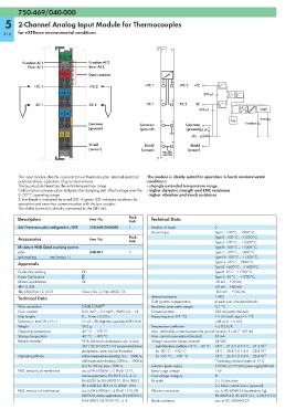
Function AI 1 A E Function AI 2
B F
Error AI 1 C G Error AI 2
D H
+TC +TC Data contacts
+TC 1 +TC 2 +TC 1 +TC 2 +TC
—TC —TC 270 pF
-TC 1 -TC 2 -TC 1 -TC 2 -TC
270 pF Logic
M M
J Error
VGL
Common Common Common Function
(ground) (ground) (ground) 20 nF
S S
Shield Shield Shield
(screen) (screen) (screen)
750-469/ 750-469/
040-000 040-000
This input module directly connects to two thermocouples. Internal electrical The module is ideally suited for operation in harsh environmental
isolation allows operation of grounded sensors. conditions:
The bus module linearizes the entire temperature range. - strongly extended temperature range
Cold junction compensation mitigates the clamping unit offset voltage over the - higher dielectric strength and EMC resistance
0–55°C operating range. - higher vibration and shock resistance
A line break is indicated by a red LED. A green LED indicates readiness for
operation and error-free communication with the bus coupler.
The shield (screen) is directly connected to the DIN rail.
Description Item No. Pack. Technical Data
Unit
2AI Thermocouple/configurable /XTR 750-469/040-000 1 Number of inputs 2
Sensor types Type L: -100°C ... +900°C;
Accessories Item No. Pack. Type K: -100°C ... +1370°C;
Unit Type J: -100°C ... +1200°C;
Miniature WSB Quick marking system Type E: -100°C ... +1000°C;
plain 248-501 5 Type T: -100°C ... +400°C;
with marking see Section 11 Type N: -100°C ... +1300°C;
Approvals Type U: -25°C ... +600°C;
Type B: +600°C ... +1800°C;
Conformity marking 1 Type R: 0°C ... +1700°C;
Korea Certification Type S: -50°C ... +1700°C;
Marine applications GL -30 mV ... +30 mV;
r UL 508 -60 mV ... +60 mV;
r ANSI/ISA 12.12.01 Class I, Div. 2, Grp. ABCD, T4 -120 mV ... +120 mV
Technical Data Internal resistance 1 MΩ
Cold junction compensation at each pair of terminal blocks
Wire connection CAGE CLAMP ® Resolution (over entire range) 0.1 °C
Cross sections 0.25 mm² ... 2.5 mm² / AWG 24 ... 14 Conversion time 320 ms (each channel)
Strip lengths 8 ... 9 mm / 0.33 in Measuring error (25 °C) < ± 6 K (volt. input < ± 2 K,
Dimensions (mm) W x H x L 12 x 62 x 100; Height from upper-edge of DIN 35 rail cold junct. < ± 4 K)
Weight 38.2 g Temperature coefficient < ± 0.2 K/K
Operating temperature -40 °C ... +70 °C Max. admissible current between the ground contacts 3 and 7: 100 mA
Storage temperature -40 °C ... +85 °C Max. current consumption (internal) 65 mA
Relative humidity 95 %, short-term condensation acc. to class Voltage via power jumper contacts 24 VDC
3K7 / IEC EN 60721-3-3 (except wind-driven under laboratory conditions +15 °C ... +35 °C 18 V ... 31.2 V (17.4 V ... 31.2 V) 1)
precipitation, water and ice formation) for -40 °C ... +55 °C 18 V ... 28.8 V (17.4 V ... 28.8 V) 1)
Operating altitude without temperature derating: 0 m ... 2000 m; for +55 °C ... +70 °C 18 V ... 26.4 V (17.4 V ... 26.4 V) 1)
with temperature derating: 2000 m ... 5000 m 1) including residual ripple of 15 %
(0.5 K/100 m); max.: 5000 m Isolation (peak value) 510 VAC or 775 VDC power supply/DIN rail
EMC immunity of interference acc. to EN 61000-6-1, -2, EN 61131-2, Rated surge voltage 1 kV
marine applications, EN 50121-3-2, -4, -5, Overvoltage category III
EN 60255-26, EN 60870-2-1, EN 61850-3, Bit width 2 x 16 bits data
IEC 61000-6-5, IEEE 1613, VDEW: 1994 2 x 8 bits control/status (optional)
EMC emission of interference acc. to EN 61000-6-3, -4, EN 61131-2, EN Vibration resistance acc. to IEC 60068-2-6 (acceleration: 5g),
60255-26, marine applications, EN 60870-2-1, EN 60870-2-2, IEC 60721-3-1, -3, EN 61131-2
EN 61850-3, EN 50121-3-2, -4, -5 Shock resistance acc. to IEC 60068-2-27