
Page 426 - Wago_AutomationTechnology_Volume3_2015_US.pdf
P. 426
750-626/040-000
5 Power Supply Filter
424 for eXTReme environmental conditions; for system and field-side power supply
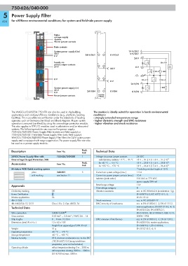
Status
13 14 voltage supply
-System
A E -Power jumper contacts
B F
C G
D H
Data contacts
+ —
System power supply (Out) 24 V/OUT 1
24 V 24 V/OUT 0 V/OUT 0 V/OUT 5
0 V 2/6
+ + 24 V
Supply via 10 nF
power jumper contacts
24 V 0 V
24 V 3/7
— — 10 nF 1 MΩ
0 V 10 nF 10 nF
0 V
+ — 24 V/IN 4
System power supply (In) 1 MΩ
24 V 24 V/IN 0 V/IN
0 V 0 V/IN 8
750-626/ Power jumper contacts 750-626/
040-000 040-000
The WAGO-I/O-SYSTEM 750 XTR can also be used in shipbuilding The module is ideally suited for operation in harsh environmental
applications and onshore/offshore installations (e.g., platforms, loading conditions:
facilities). This is possible via certification under the standards of leading - strongly extended temperature range
agencies such as Germanischer Lloyd and Lloyds Register. Proper system - higher dielectric strength and EMC resistance
operation is ensured (certified) by using this overvoltage protection module. - higher vibration and shock resistance
This also applies to XTR I/O modules used in substations and/or telecontrol
systems. The following modules are required for power supply:
750-626/040-000 Power Supply Filter (system and field supply) or
750-624/040-001 Field-Side Power Supply Filter (only field supply).
WAGO's 750-626/040-000 Power Supply Filter filters the 24 V system power
supply and is equipped with surge suppression. The power supply filter can also
be used as a power supply module.
Description Item No. Pack. Technical Data
Unit
24VDC Power Supply Filter with 750-626/040-000 1 Voltage via power jumper contacts 24 VDC
Overvoltage (Surge) Protection /XTR under laboratory conditions +15 °C ... +35 °C 18 V ... 31.2 V (17.4 V ... 31.2 V) 1)
Accessories Item No. Pack. for -40 °C ... +55 °C 18 V ... 28.8 V (17.4 V ... 28.8 V) 1)
Unit for +55 °C ... +70 °C 18 V ... 26.4 V (17.4 V ... 26.4 V) 1)
Miniature WSB Quick marking system 1) including residual ripple of 15 %
plain 248-501 5 Current via system voltage (max.) 1.5 A
with marking see Section 11 Current via power jumper contacts (max.) 10 A
Isolation (peak value) 510 VAC or 775 VDC
power supply/DIN rail
Approvals Rated surge voltage 1 kV
Overvoltage category III
Conformity marking 1 Vibration resistance acc. to IEC 60068-2-6 (acceleration: 5g),
Korea Certification EN 60870-2-2, IEC 60721-3-1, -3,
Marine applications GL EN 61131-2
r UL 508 Shock resistance acc. to IEC 60068-2-27
r ANSI/ISA 12.12.01 Class I, Div. 2, Grp. ABCD, T4 EMC immunity of interference acc. to EN 61000-6-1, -2, EN 61131-2,
Technical Data marine applications, EN 50121-3-2, -4, -5,
EN 60255-26, EN 60870-2-1,
Wire connection CAGE CLAMP ® EN 61850-3, IEC 61000-6-5, IEEE 1613,
Cross sections 0.25 mm² ... 2.5 mm² / AWG 24 ... 14 VDEW: 1994
Strip lengths 8 ... 9 mm / 0.33 in EMC emission of interference acc. to EN 61000-6-3, -4, EN 61131-2,
Dimensions (mm) W x H x L 12 x 62 x 100 EN 60255-26, marine applications,
Height from upper-edge of DIN 35 rail EN 60870-2-1, EN 61850-3,
Weight 51 g EN 50121-3-2, -4, -5
Operating temperature -40 °C ... +70 °C
Storage temperature -40 °C ... +85 °C
Relative humidity 95 %, short-term condensation acc. to class 3K7
/ IEC EN 60721-3-3 (except wind-driven
precipitation, water and ice formation)
Operating altitude without temperature derating: 0 m ... 2000 m;
with temperature derating: 2000 m ... 5000 m
(0.5 K/100 m); max.: 5000 m