
Page 427 - Wago_AutomationTechnology_Volume3_2015_US.pdf
P. 427
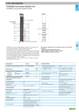
750-1605/040-000

           Field-Side Connection Module 16+                                                                        5

           for eXTReme environmental conditions; 24 VDC                                                             425


                                750-1605/                        750-1605/
                                                                  040-000
                                040-000
                                13  14
                                           Data contacts
                       ®
               CAGE CLAMP S
                  connection                                +    1   9    +
                      24 V                 24 V
                                 1  9                            2   10
                                                            +             +
                      24 V                 24 V
                                 2  10
                                                                 3   11
                                                            +             +
                      24 V       3  11     24 V
                                                         + 24 V
                                                                 4   12
                                                            +             +
                      24 V                 24 V
                                 4  12                           5   13
                                                            +             +
                      24 V                 24 V
                                 5  13
                                                           0 V
                                                                 6   14
                                                            +             +
                      24 V                 24 V
                                 6  14
                                                                 7   15
                                                            +             +
                      24 V                 24 V
                                 7  15
                                                                 8   16
                                                            +             +
                      24 V                 24 V
                                 8  16
                                          Power jumper contacts
                                                                                                                    5
           The field side connection module provides 24 V power for the inputs of the   The module is ideally suited for operation in harsh environmental
           16-channel input module 750-1405/040-000, for example.  conditions:
           This eliminates the need for additional terminal blocks.  - strongly extended temperature range
           The 24 V supply and 0 V potential are derived from the internal power jumper  - higher dielectric strength and EMC resistance
           contacts of an adjacent upstream I/O module. A connection of the potentials   - higher vibration and shock resistance
           to the downstream I/O modules is made automatically via the power jumper
           contacts when snapping the I/O modules together. The 24 V power is provided
                                ®
           to all 16 field-side CAGE CLAMP  S connections and the 0 V potential passed
           through without being used by the module.
           An operating tool with a 2.5 mm blade (210-719) is required to open the
                    ®
           CAGE CLAMP S connections.
           Description                 Item No.        Pack.    Technical Data
                                                       Unit
           Field-Side Connection Module 16+ /XTR  750-1605/040-000  1  Voltage via power jumper contacts  24 VDC
                                                                  under laboratory conditions +15 °C ... +35 °C  18 V ... 31.2 V (17.4 V ... 31.2 V) 1)
           Accessories                 Item No.        Pack.      for -40 °C ... +55 °C   18 V ... 28.8 V (17.4 V ... 28.8 V) 1)
                                                       Unit       for +55 °C ... +70 °C   18 V ... 26.4 V (17.4 V ... 26.4 V) 1)
           Miniature WSB Quick marking system                                             1)  including residual ripple of 15 %
                       plain           248-501         5        Current via power jumper contacts (max.)  10 A
                       with marking    see Section 11           Isolation (peak value)    510 VAC or 775 VDC
                                                                                          power supply/DIN rail
           Operating tool, with partially insulated   210-719  50  Rated surge voltage    1 kV
           shaft, type 1, blade (2.5 x 0.4) mm                  Overvoltage category      III
           Approvals                                            Vibration resistance      acc. to IEC 60068-2-6 (acceleration: 5g),
                                                                                          EN 60870-2-2, IEC 60721-3-1, -3,
           Conformity marking       1                                                     EN 61131-2
           Marine applications      GL                          Shock resistance          acc. to IEC 60068-2-27
           r UL 508                                             EMC immunity of interference  acc. to EN 61000-6-1, -2, EN 61131-2,
           r ANSI/ISA 12.12.01      Class I, Div. 2, Grp. ABCD, T4                        marine applications, EN 50121-3-2, -4, -5,
           Technical Data                                                                 EN 60255-26, EN 60870-2-1,
                                                                                          EN 61850-3, IEC 61000-6-5, IEEE 1613,
                                             ®
           Wire connection          CAGE CLAMP  S                                         VDEW: 1994
           Cross sections           0.25 mm² ... 1.5 mm² / AWG 24 ... 16  EMC emission of interference  acc. to EN 61000-6-3, -4, EN 61131-2,
           Strip lengths            8 ... 9 mm / 0.33 in                                  EN 60255-26, marine applications,
           Dimensions (mm) W x H x L  12 x 62 x 100                                       EN 60870-2-1, EN 61850-3,
                                    Height from upper-edge of DIN 35 rail                 EN 50121-3-2, -4, -5
           Weight                   40.2 g
           Operating temperature    -40 °C ... +70 °C
           Storage temperature      -40 °C ... +85 °C
           Relative humidity        95 %, short-term condensation acc. to class 3K7
                                    / IEC EN 60721-3-3 (except wind-driven
                                    precipitation, water and ice formation)
           Operating altitude       without temperature derating: 0 m ... 2000 m;
                                    with temperature derating: 2000 m ... 5000 m
                                    (0.5 K/100 m); max.: 5000 m