
Page 637 - Wago_AutomationTechnology_Volume3_2015_US.pdf
P. 637
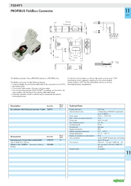
750-971

           PROFIBUS Fieldbus Connector                                                                             11

                                                                                                                    635


                                                            72.8 mm                     B
                                                                              8.4 mm        S1
                                                          Thread ø 4-40                 A
                                               16.2 mm                                  B           390 Ω 390 Ω 220 Ω

                                                                                        A
                                                                                                    1  2  3  4  5
                                                   2.9 mm                                            6  7  8  9
                                                                                                     Male connector


                                               43.6 mm
                                                            12 mm


                                                                    25 mm
                                                   5.2 mm           35 mm
                                                                53.1 mm
                                                                                                          21 mm
                                                                                                            6 mm
                                                                                                      7 mm


           The fieldbus connector links a PROFIBUS device to a PROFIBUS line.  For the first and last station on the bus, the switch must be set to “ON”
                                                               (terminating resistor activated, outgoing bus line disconnected).
           The fieldbus connector has the following features:  Switch setting to “OFF” for the intermediate stations on the bus
           • Compact design. It is particularly well-suited for the connection to an S7 PLC.  (terminating resistor deactivated).
           • No losable parts.
           • 2 horizontal cable entries. One input and one output.
                                       ®
           • Fast and maintenance-free CAGE CLAMP  connection, can be held in the
            open position with the help of an actuation slide mechanism.
           • Externally operable switch to activate and/or deactivate the network
            terminating resistor.


           Description                      Item No.   Pack.    Technical Data
                                                       Unit
           Bus connector with D-Sub male connector; 9 poles  750-971  1  Double cable input  Ø 8.5 mm
                                                                Data transmission rate    corresponding to PROFIBUS specification
                                                                                          up to 12 Mbits/s
                                                                Power supply              4.75 V ... 5.25 V DC
                                                                Max. current consumption (internal)  5 mA
                                                                Fixing screw              UNC- 2 A 4-40
                                                                Max. tightening torque    0.4  Nm
                                                                Housing material          PC-V0
                                                                Housing color             light gray
                                                                Degree of protection      IP20
                                                                Ambient operating temperature  0°C ... +60°C
                                                                Storage temperature       -25 °C ... +85 °C
           Accessories                      Item No.   Pack.    Relative air humidity (no condensation)  95 %
                                                       Unit     Wire connection           CAGE CLAMP  terminal strips with locking
                                                                                                  ®
           Operating tool, with partially insulated shaft,   210-719  50                  slide (218 Series)
           Type 1, blade (2.5 x 0.4) mm                         Cross sections            0.08 mm² ... 0.5 mm² / AWG 28 ... 20
           Test pin, 1 mm / 0.039 in  Test wire for soldering  735-500  1                 sep. connection 0.75 mm² / AWG 18
           Markers                                                                        possible
                                                                Stripped length           see graphic
                                                                                                                    11