Page 20 - Parker - Compact Hydraulic Cylinders
P. 20

Catalog HY08-1137-7/NA                            Compact Hydraulic Cylinders
            Switch Mounting / End-of-Stroke Location          Series CHE


   View
   Table of
  Contents


                                                                                                                        CHE


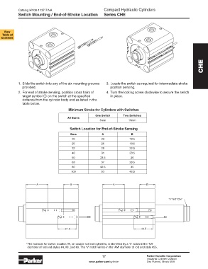
            1. Slide the switch into any of the six mounting grooves   3. Locate the switch as required for intermediate stroke
              provided.                                           position sensing.
            2. For end of stroke sensing, position cross hairs of   4. Turn the locking screw clockwise to secure the switch
              target symbol      on the switch at the specified   in place.
              distance from the cylinder body end as listed in the
              table below.

                                         Minimum Stroke for Cylinders with Switches
                                                         One Switch       Two Switches
                                         All Bores
                                                            5mm              10mm

                                          Switch Location for End-of-Stroke Sensing
                                          Bore               A                B
                                           20                24              18.5
                                           25                25              19.5
                                           32                28              22.5
                                           40                31              23.5
                                           50               33.5              26
                                           63                37              29.5
                                           80               42.5              35
                                           100               53              42.5


                       A                  B                         A                  B


                                                                                                     ‘V’ NOTCH   1


                                       31.5                                         31.5


                1  The rod side for switch location ‘B’, on double rod end cylinders, is identified by a ‘V’ notch in the ‘NA’
                 diameter of rod end styles #4, #8, and #9. The ‘V’ notch will be in the ‘AM’ diameter of rod end style #55.


                                                             17                        Parker Hannifin Corporation
                                                                                       Industrial Cylinder Division
                                                     www.parker.com/cylinder           Des Plaines, Illinois USA
   15   16   17   18   19   20   21   22   23   24   25