
Page 22 - Parker - Compact Hydraulic Cylinders
P. 22
Catalog HY08-1137-7/NA Compact Hydraulic Cylinders
CPS Sensors Series CHE
Operating Instructions Minimum Stroke
• Read the operating instructions before starting To ensure that both CPS mounting screws engage in
View operation. the cylinder body, the minimum stroke for each bore and
Table of sensor combination must be observed.
Contents • Connection, assembly, and settings should be
accomplished only by competent technicians. Bore Minimum Stroke
• This sensor does not qualify as a safety component in Ø CPS-32 CPS-64 CPS-96 CPS-128 CPS-160
accordance with EU machine guidelines. 20 2 34 N/A N/A N/A
• Use power source according to IEC/DIN EN 60204-1. 25 – 32 64 96 N/A
• Do not use ferrite components in the direct 32 – 26 58 90 122
environment of the CPS. 40 – 22 54 86 118
Proper Use 50 – 17 49 81 113 CHE
The measurement signal is output via analog voltage or 63 – 10 42 74 106
current. The yellow LED lights when the piston is within 80 – – 31 63 95
the measurement range (signal strength indicator). The 100 – – 13 45 77
desired Zero Point and End Point of the measurement
range can be set precisely via the Teach-In button. Cordset for CPS Sensors
The 4-pin, 8 mm threaded connector on this cordset can
Starting Operation be used only with CPS Sensors.
1. Positioning and securing the sensor:
Connect the sensor to operating voltage (see Specifi ca- Cordset Specifications
tions and Wiring Connection diagram). Insert the sensor Connector .................. Oil resistant polyurethane body
into the cylinder mounting slot from above. Move the material, PA 6 (Nylon) contact carrier,
piston into the desired Zero Point position. The yellow spacings to VDE 0110 Group C
LED lights when the piston is in the measurement range. Contacts ..................... Gold plated brass
Move the sensor along the slot until the LED switches Cord Construction ...... Oil resistant black PUR jacket, non-
off. Move the sensor back again until the LED lights. wicking, non-hygroscopic, 300V. Cable
Secure the sensor appropriately. The measurement end is stripped and tinned.
range does not need to be set. If the user does not
Teach-In the measurement range, the maximum Conductors................. Extra high flex stranding,
possible range is used as a default. PVC insulation.
Temperature ............... -40°C to +90°C (-40°F to +176°F)
2. Teach-In of measurement range (option): Protection ................... NEMA 6 / IP67
Move the piston into the desired Zero Point position.
Press the teach button for 2 seconds; LED blinks Cable Length .............. 2m (6.56 ft) or 5m (16.40 ft)
(3x/second). Release the Teach-In button; the Zero Point
is stored. Set the piston position for the “End Point” of
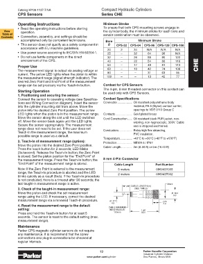
the measurement range. Press the Teach-In button; the 8 mm 4-Pin Connector
“End Point” of the measurement range is stored. Cable Length Part Number
Note: If the Zero Point is external to the measurement 5 meters 096043T005
range, the Teach-In procedure is aborted and the LED 2 meters 096043T002
blinks quickly as a result (6x/s). If the Teach-In procedure
is not concluded, there is a timeout after 90 seconds; the
last taught-in measurement range is active. M8x1
CABLE LENGTH (m)
3. Check of the taught-in measurement range: (SEE TABLE)
Move the piston and check the set measurement Ø .354
range using the LED. If necessary, correct the desired 9.0
measurement range via a renewed Teach-In procedure. Ø .177 .276
4.5 7.0
4. Reset the measurement range to the default
setting: CABLE MINIMUM 1.26
BEND RADIUS:
Press and hold the Teach-In button for at least 5 100mm 32.0
seconds. The sensor is reset to the default setting (max.
measurement range).
Maintenance
Parker CPS magnetic cylinder sensors do not require
any maintenance. It is recommend that the screw
connections and plug-in connections be checked at
regular intervals.
19 Parker Hannifin Corporation
Industrial Cylinder Division
www.parker.com/cylinder Des Plaines, Illinois USA