
Page 26 - Parker - Compact Hydraulic Cylinders
P. 26
Catalog HY08-1137-7/NA Compact Hydraulic Cylinders
Model Code & Standard Specifications Series CHD
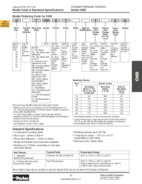
Model Ordering Code for CHD
32 T CHD B T 9 A 25
View
Table of
Contents
Bore Double Mounting Series Piston Ports Seals Special Piston Piston Piston Stroke
Dia. Rod Style Modification Rod Rod Rod
Cylinder Thread Thread Thread
Style Style Type
(For Dbl.
Rod)
Specify: Use “K” CHD Specify: Specify: Leave Use Specify: Specify: Specify: Specify
(Bore only if B = Non- T = SAE blank “S” for 4 = Small 4 = Small A = Stroke
dia. in double Specify: magnetic Ports for std. Special Male Male Imperial Length
mm) rod T = Std. Mount piston U = Nitrile Modifi- 8 = Inter- 8 = Inter- (UNF or Required
4
20 cylinder TN = Std. Mount with Add NPTF Seals cation mediate mediate UNC) in mm .
25 is pilot gland option: Ports V = other Male Male M =
required.
than rod
32 TR = Std. Mount with 9 = Non- R = Fluoro- end, and 9 = 9 = Metric 3
carbon
40 cap pilot magnetic BSPP specify Female Female
50 A = Imperial thread piston Ports modifi- 55 = 55 =
with
63 tapped both ends bronze M = cation. Flange Flange
Manifold
Coupler
Coupler
80 AN = Imperial tapped cap & Ports 1 3 = 3 =
with pilot gland
AR = Imperial tapped gland. Special 2 Special 2
with cap pilot
M = Metric thread
tapped both ends CHD
MN = Metric tapped
with pilot gland Maximum Stroke
MR = Metric tapped Bore Stroke in mm
5
with cap pilot Ø
Mounting
Bolt-on
C = Foot Mount Styles T, TN, Mounting Mounting
Styles
CN = Foot Mount with TR, A, AN, AR C & CN Styles 6
pilot gland M, MN, MR J & H
J = Head Rectangular
Flange 20 50 N/A 50
H = Cap Rectangular 25 60 50 60
Flange 32 115 100 100
Shaded boxes identify required model number fields. 40 115 100 100
Rod Piston Rod 1 Manifold ports are only available on Foot Mounting Styles C & 50 125 100 100
Ø Weight per mm CN. See Mounting Styles C & CN Dimension Pages for minimum 63 115 100 100
stroke with Manifold Ports.
12 0.001 2 To order thread style 3, specify “3” and give the desired 80 115 N/A 100
14 0.001 dimensions for KK, A, and W (or WP depending on mounting) or 5 Intermediate strokes in 1mm increments are available.
furnish a dimensioned sketch. 6
18 0.002 3 Always use M for rod style 55. Longer strokes (up to maximum lengths for Mounting Styles T,
TN, TR, A, AN, AR, M, MN & MR) are available at increased
22 0.003 4 See Maximum Stroke Chart at right. manufacturing lead times. Contact the factory.
28 0.005
36 0.008 Standard Specifications
45 0.012 • 13 Standard mounting styles • Working pressure up to 207 bar
• Bore sizes – 20mm to 80mm • Temperature range – -23°C to +121°C
• Piston Rod Diameter – 12mm to 45mm (depending on seal class)
Bore Rod Double Rod Cylinders • Single and double rod construction available • Reference ISO 16656: 2004
Ø Ø
Basic Weight at Zero Stroke Per Basic Weight Per Basic Weight Per • Strokes up to 100mm depending on bore size
mm at Zero Stroke mm at Zero Stroke mm (see table above)
T TN A, M AN, MN
Stroke Stroke Stroke
J C CN Seal Classes Typical Fluids Temperature Range
20 12 0.60 0.61 0.64 0.65 0.013 0.87 0.014 - - - 1 – Standard Hydraulic Oil, MIL-H-5606 Oil -23°C (-10°F) to +100°C (+212°F)
25 14 0.83 0.85 0.87 0.89 0.017 1.21 0.018 0.75 0.77 0.016 Nitrile & Polyurethane
32 18 1.46 1.48 1.52 1.54 0.026 1.98 0.027 1.47 1.50 0.028 High Temperature -23°C (-10°F) to +121°C (+250°F)
40 22 1.97 2.01 2.08 2.11 0.032 2.92 0.034 2.03 2.07 0.036 5 – Optional (At extra cost) Class 5 seals may be operated up to +204°C
Fluorocarbon Seals
50 28 2.81 2.87 2.99 3.05 0.041 4.40 0.043 3.02 3.08 0.049 (+400°F) with reduced service life
63 36 4.52 4.61 4.75 4.83 0.055 6.53 0.059 5.10 5.19 0.071
80 45 7.99 8.12 8.28 8.42 0.080 11.5 0.085 - - - Note: Class 5 seals are not suitable for use with Skydrol fluid, but can be used with hydraulic oil if desired.
23 Parker Hannifin Corporation
Industrial Cylinder Division
www.parker.com/cylinder Des Plaines, Illinois USA