
Page 8 - Parker - Compact Hydraulic Cylinders
P. 8
Catalog HY08-1137-7/NA Compact Hydraulic Cylinders
Model Code & Standard Specifications Series CHE
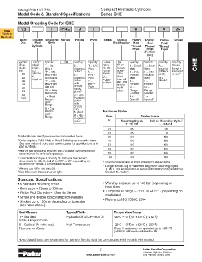
Model Ordering Code for CHE
32 T CHE 3 T 9 A 25
View
Table of
Contents
Bore Double Mounting Series Piston Ports Seals Special Piston Piston Piston Stroke
Dia. Rod Style Modification Rod Rod Rod
Cylinder Thread Thread Thread
Style Style Type
(For Dbl.
Rod)
Specify: Use “K” Specify: CHE Specify: Specify: Leave Use Specify: Specify: Specify: Specify
(Bore only if T = Std. 3 = T = SAE blank “S” for 4 = Small 4 = Small A = Stroke CHE
dia. in double Mount Magnetic Ports for std. Special Male Male Imperial Length
mm) rod TN = Std. piston 1 U = Nitrile Modifi- 8 = Inter- 8 = Inter- (UNF or Required
20 cylinder Mount with 5 = NPTF Seals cation mediate mediate UNC) in mm .
5
25 is pilot gland Magnetic Ports V = other Male Male M =
required.
than rod
32 TR = Std. piston R = Fluoro- end, and 9 = 9 = Metric 4
carbon
40 Mount with with BSPP specify Female Female
bronze
50 cap pilot cap & Ports modifi- 55 = 55 =
63 CA = Side gland 2 cation. Flange Flange
Coupler
Coupler
Lug Mount
80 J = Head 9 = Non- 3 = 3 =
100 Rectan- magnetic Special 3 Special 3
gular piston
Flange with
bronze
H = Cap cap,
Rectan- & gland Maximum Stroke
gular
6
Flange B = Non- Bore Stroke in mm
magnetic
piston. Ø Mounting Styles Bolt-on Mounting Styles
7
T, TN, TR J, H & CA
20 100 50
25 100 75
Shaded boxes identify required model number fields. 32 150 100
1 Order required Solid State or Reed Switches as separate items. 40 150 100
See reed switch & solid state switch pages for specifications and 50 150 100
part numbers.
2 Bronze cap and gland required for CPS linear cylinder position 63 165 100
Rod Piston Rod sensor (must be ordered separately). 80 165 100
Ø Weight per mm 100 125 100
3 To order thread style 3, specify “3” and give the desired
12 0.001 dimensions for KK, A, and W (or WP or WR depending on 6 Intermediate strokes in 1mm increments are available.
14 0.001 mounting) or furnish a dimensioned sketch. 7 Longer strokes (up to maximum lengths for Mounting Styles
4 Always use M for rod style 55.
18 0.002 T, TN & TR) are available at increased manufacturing lead times.
5 See Maximum Stroke chart at right. Contact the factory.
22 0.003
28 0.005
36 0.008 Standard Specifications
45 0.012 • 6 Standard mounting styles • Working pressure up to 140 bar (depending on
bore size)
56 0.019 • Bore sizes – 20mm to 100mm
• Piston Rod Diameter – 12mm to 56mm • Temperature range – -23°C to +121°C (depending on
seal class)
• Single and double rod construction available
• Strokes up to 150mm depending on bore size • Reference ISO 16656: 2004
(see table above).
Seal Classes Typical Fluids Temperature Range
1 – Standard Hydraulic Oil, MIL-H-5606 Oil -23°C (-10°F) to +100°C (+212°F)
Nitrile & Polyurethane
5 – Optional (At extra cost) High Temperature -23°C (-10°F) to +121°C (+250°F)
Fluorocarbon Seals Class 5 seals may be operated up to +204°C
(+400°F) with reduced service life
Note: Class 5 seals are not suitable for use with Skydrol fluid, but can be used with hydraulic oil if desired.
5 Parker Hannifin Corporation
Industrial Cylinder Division
www.parker.com/cylinder Des Plaines, Illinois USA