
Page 35 - Parker - General Technical
P. 35
4300 Catalog General Technical
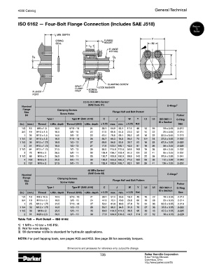
ISO 6162 — Four-Bolt Flange Connection (Includes SAE J518)
Return
To
Index
2.5 to 31.5 MPa Series 1)
(SAE Code 61) 3)
Nominal O-Rings
Flange Clamping Screws
Size Screw Holes Flange Half and Bolt Pattern
D3 Parker
Type I Type II (SAE J518) C J W Y L5 L6 ISO 3601-1 O-Ring
2)
ID x Section
(in.) (mm.) Thread t 1Min. depth Thread (UNC) t 1Min. depth ± 0.25 max. min. ± 0.25 Ref. Size
1/2 13 M8 x 1.5 12.5 5/16 - 18 24 38.1 54.9 53.1 17.5 46 13 19 19 x 3.55 2-210
3/4 19 M10 x 1.5 16.5 3/8 - 16 22 47.6 65.8 64.3 22.3 52 14 22 25 x 3.55 2-214
1 25 M10 x 1.5 14.5 3/8 - 16 22 52.4 70.6 69.1 26.2 59 16 22 32.5 x 3.55 2-219
1 1/4 32 M10 x 1.5 16.5 7/16 - 14 28 58.7 80.3 78.5 30.2 73 14 4) 24 37.5 x 3.55 2-222
1 1/2 38 M12 x 1.75 19.5 1/2 - 13 27 69.9 94.5 93.0 35.7 83 16 25 47.5 x 3.55 2-225
2 51 M12 x 1.75 19.5 1/2 - 13 27 77.8 103.1 100.1 42.9 97 16 26 56 x 3.55 2-228
2 1/2 64 M12 x 1.75 21.5 1/2 - 13 30 88.9 115.8 112.8 50.8 109 19 38 69 x 3.55 2-232
3 76 M16 x 2 28.5 5/8 - 11 30 106.4 136.7 133.4 61.9 131 22 41 85 x 3.55 2-237
3 1/2 89 M16 x 2 28.5 5/8 - 11 33 120.7 153.9 150.9 69.9 140 22 28 97.5 x 3.55 2-241
4 102 M16 x 2 25.5 5/8 - 11 30 130.2 163.6 160.3 77.8 152 25 35 112 x 3.55 2-245
5 127 M16 x 2 27.5 5/8 - 11 33 152.4 182.6 185.7 92.1 181 28 41 136 x 3.55 2-253
40 MPa Series 1)
(SAE Code 62) 3)
Nominal O-Rings
Flange Clamping Screws
Size Screw Holes Flange Half and Bolt Pattern
D3 Parker
Type I Type II (SAE J518) C J W Y L5 L6 ISO 3601-1 O-Ring
2)
ID x Section
(in.) (mm.) Thread t 1Min. depth Thread (UNC) t 1Min. depth ± 0.25 max. min. ± 0.25 Ref. Size
1/2 13 M8 x 12.5 14.5 5/16 - 18 21 38.1 57.2 55.6 18.2 48 16 22 19 x 3.55 2-210
3/4 19 M10 x 1.5 16.5 3/8 - 16 24 47.6 72.1 70.6 23.8 60 19 28 25 x 3.55 2-214
1 25 M12 x 1.75 21.5 7/16 - 14 27 52.4 81.8 80.3 27.8 70 24 33 32.5 x 3.55 2-219
1 1/4 32 M12 x 1.75 18.5 1/2 - 13 25 58.7 96.0 94.5 31.8 78 27 38 37.5 x 3.55 2-222
1 1/2 38 M16 x 2 25.5 5/8 - 11 35 69.9 114.3 111.3 36.5 95 30 43 47.5 x 3.55 2-225
2 51 M20 x 2.5 33.5 3/4 - 10 38 77.8 134.9 131.8 44.5 114 37 52 56 x 3.55 2-228
Table T25 — Port Detail — ISO 6162
1) 1 MPa = 10 bar = 145 PSI.
2) Not for new design.
3) 90 durometer nitrile is standard for hydraulic applications.
NOTE: For port tapping tools, see pages R32 and R33. See page S8 for assembly torques.
Dimensions and pressures for reference only, subject to change.
T35 Parker Hannifin Corporation
Tube Fittings Division
Columbus, Ohio
http://www.parker.com/tfd