
Page 30 - Parker - General Technical
P. 30
4300 Catalog General Technical
How to Order 4-Bolt Hydraulic Flanges Return
To
TFD Standard Nomenclature Construction Catalog
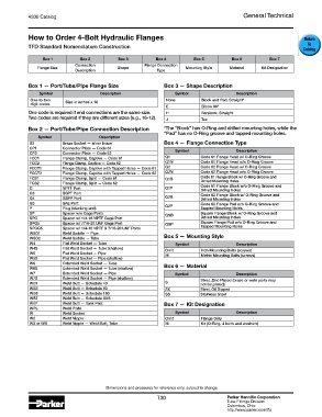
Box 1 Box 2 Box 3 Box 4 Box 5 Box 6 Box 7
Connection Flange Connection
Flange Size Shape Mounting Style Material Kit Designation
Description Type
Box 1 — Port/Tube/Pipe Flange Size Box 3 — Shape Description
Symbol Description Symbol Description
One-to-two Size in inches x 16 None Block and Pad, Straight*
digit codes
E Elbow 90°
One code is required if end connections are the same size. H Barstock, Straight
Two codes are required if they are different sizes (e.g., 16-12). J Tee
Box 2 — Port/Tube/Pipe Connection Description *The “Block” has O-Ring and drilled mounting holes, while the
“Pad” has no O-Ring groove and tapped mounting holes.
Symbol Description
B3 Braze Socket — silver braze Box 4 — Flange Connection Type
CP1 Connector Plate — Code 61
CP2 Connector Plate — Code 62 Symbol Description
FCC1 Flange Clamp, Captive — Code 61 Q1 Code 61 Flange Head w/ O-Ring Groove
FCC2 Flange Clamp, Captive — Code 62 Q1N Code 61 Flange Head w/o O-Ring Groove
FCCT1 Flange Clamp, Captive with Tapped Holes — Code 61 Q2 Code 62 Flange Head w/ O-Ring Groove
FCCT2 Flange Clamp, Captive with Tapped Holes — Code 62 Q2N Code 62 Flange Head w/o O-Ring Groove
FCS1 Flange Clamp, Split — Code 61 Q1B Code 61 Flange Block w/ O-Ring Groove and
FCS2 Flange Clamp, Split — Code 62 Drilled Mounting Holes
G NPTF Port Q1P Code 61 Flange Block w/o O-Ring Groove and
Drilled Mounting Holes
G3 BSPT Port Code 62 Flange Block w/ O-Ring Groove and
G4 BSPP Port Q2B Drilled Mounting Holes
G5 SAE Port Code 62 Flange Pad w/o O-Ring Groove and
P Plug (blanking end) Q2P Tapped Mounting Holes
SP Spacer w/o Gage Ports QSB Square Flange Block w/ O-Ring Groove and
SPG Spacer w/ 1/4-18 NPTF Gage Port Drilled Mounting Holes
SPG5 Spacer w/ 7/16-20 UNF Gage Port QSP Square Flange Pad w/o O-Ring Groove and
SPGG5 Spacer w/ 1/4-18 NPTF & 7/16-20 UNF Ports Tapped Mounting Holes
WSD1 Weld Saddle — Pipe Box 5 — Mounting Style
WSD2 Weld Saddle — Tube
W4 Flat Weld Socket — Tube Symbol Description
W4S Flat Weld Socket — Tube (shallow) Omit Inch Mounting Bolts (screws)
W5 Flat Weld Socket — Pipe M Metric Mounting Bolts (screws)
W5S Flat Weld Socket — Pipe (shallow)
W6 Extended Weld Socket — Tube Box 6 — Material
W6S Extended Weld Socket — Tube (shallow)
W7 Extended Weld Socket — Pipe Symbol Description
W7S Extended Weld Socket — Pipe (shallow) Steel, Zinc Plated (braze or weld parts may
WB1 Weld Butt — Schedule 40 S not be plated)
WB3 Weld Butt — Schedule 80 SX Steel, Oil Dipped
WB5 Weld Butt — Schedule 160 SS Stainless Steel
WB7 Weld Butt — Schedule XXS
WBT Weld Butt — Tank Pilot Box 7 — Kit Designation
WPL Weld Plate
W Weld Socket Symbol Description
W2 Weld Nipple Omit Flange Only
W3 or WB Weld Nipple — Weld Butt, Tube M Kit (O-Ring, 4 bolts and washers)
Dimensions and pressures for reference only, subject to change.
T30 Parker Hannifin Corporation
Tube Fittings Division
Columbus, Ohio
http://www.parker.com/tfd