
Page 4 - Parker - General Technical
P. 4
4300 Catalog General Technical
Size S
Return
To
Proper material, type and size of tubing and fittings for Index
a given application is critical for efficient and trouble free
operationof the fluid system. Selection of proper tubing and
fittings involves determining the correct flow diameter, then
selecting the correct material and the optimum tube size
(O.D. and wall thickness).
Proper sizing for various parts of a hydraulic system results
in an optimum combination of efficient and cost
effective performance. A tube or fitting that is too small
causes high fluid velocity, which has many detrimental
effects. In suction lines, it causes cavitation which starves
and damages pumps. In pressure lines, it causes high
friction losses and turbulence, both resulting in
high pressure drops and heat generation. High heat
accelerates wear in moving parts and rapid aging of seals
and hoses, all resulting in reduced component life. High
heat generation also means wasted energy, and hence,
low efficiency.
Too large of a tube or fitting increases system cost. Thus,
optimum sizing is very critical. The following is a simple
procedure for sizing of tube and fittings.
Step 1: Determine Required Flow Diameter
Use Tables T1 and T2 to determine recommended flow
diameter for the required flow rate and type of line.
The table is based on the following recommended flow
velocities:
Pressure lines — 25 ft./sec. or 7.62 meters/sec.
Return lines — 10 ft./sec. or 3.05 meters/sec.
Suction lines — 4 ft./sec. or 1.22 meters/sec.
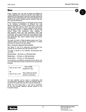
If you desire to use different velocities than the above, use
one of the following formulae to determine the required flow
diameter.
Flow in GPM
Tube I.D. (in.) = 0.64
Velocity in ft../sec.
OR
Flow in liters per minute
Tube I.D. (in.) = 4.61
Velocity in meters/sec.
The flow diameter will be used in combination with
the temperature, application, media and pressure data to
determine the proper tube size (O.D. and wall thickness).
NOTE: The tube fitting dash (-) size will be dependent
on the tube outside diameter selected based on the
S.T.A.M.P. criteria.
T4 Parker Hannifin Corporation
Tube Fittings Division
Columbus, Ohio
http://www.parker.com/tfd