
Page 67 - Parker - Gearheads and Gearmotors
P. 67
Specifications Operating Control Signals
Part Number 11564041 11564045 and Indicators
24 to 48 24 to 48 Input Analog Control
Input Power Bus ±10 Volts
VDC VDC Signal
Continuous Output 450 watts 1 1350 watts 1 Digital Input Commands Rs-232, SPI
Power (Max.) Peak Current limit Software adjustable
Continuous Output 1 1 Continuous Current Limit Software adjustable
Current 10 amps 15 amps 5V logic, optically
20 amps 1 Drive Enable/Reset
Peak Output Current 40 amps 1 isolated
(1 sec typ.)
Scale Factor ( A / V ) 2 6 (+) Travel Limit 5V logic, optically
isolated
Input Bus Input Bus
Voltage @ Continuous Voltage – 3 Voltage – 3 (-) Travel Limit 5V logic, optically
Output Current isolated
Volts Typ. Volts Typ.l
Max Heat Sink Disables if Disables if Brake 5V logic, optically
isolated
Temperature >70°C >70°C
Current Loop Fault and/or Brake Status 5V logic, optically
isolated
Bandwidth 2 kHz Typ. 2 kHz Typ. Drive Enabled indicator Green LED
Switching Frequency 40 kHz 40 kHz Brake Indicator Red LED
Minimum Maintenance 100 UH 100 UH
Weight 25 oz 25 oz Fault Indicator Red LED
1 Depends on ambient operating temperature and heat sink. For the Digital Hall Effect Sensors 3 channels,+5
Volts,Gnd
>10 amperes continuous output, we recommend forced convection
cooling with a minimum airflow of 100 CFM. Consult factory for
assistance.
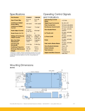
Mounting Dimensions
(inches)
3.495 ±0.005 ~0.4
0.120 dia. (6 places) ~0.7
PWR
0.48 JP1 J3 TB1
JP2
1.15 0.23 BRK JP3 FAN
JP4
1.50 0.23 FLT TB2 MTR ~1.3 ~1.5
2.03 ENB JP5 ~2.1
2.35
Enable
S2 TB3
3.59 Reset SPI J4 HALLS
S1 Re-boot
J2
3.931
RS-232 J5
I/O ±0.005
J1 D-SUB
1
0.25 JP6
JP7
JP8
JP9
0.141 ±0.005 7.655 ±0.005 0.25
0.500 8.655 ±0.005
1.375 (top of heat sink)
1.60
(max.
0.90 height)
0.57
0.30
Parker Hannifin Corporation • Electromechanical Automation Division • 800-358-9070 • www.parkermotion.com 67