Page 60 - Colder Products Company - Catalog
P. 60

Liquid Flow Rate Information for Couplings
                                                                                             Q  =  Flow rate in gallons per minute
            The chart below shows the flow rate for CPC couplings. Each coupling was tested with water at 70°F   C V   =  Average coefficient across various
            (21°C). To determine flow rates for specific coupling configurations use the formula at the right.       flow rates (see chart)
                                                                                              P =  Pressure drop across  coupling (psi)
            C V  VALUES FOR EFC12 COUPLINGS                                                  S  =  Specific gravity of liquid
                            EFC12   EFCD12    EFC12   EFCD12    EFC12   EFCD12    EFC12   EFCD12   EFC12    EFCD12
             BODIES  INSERTS  20004  20004   20006    20006    22004    22004    22006    22006    24004    24004
                EFCD10412    0.51     0.51     0.51     0.51    0.50     0.45     0.50     0.50     0.51     0.51
                EFCD10612    0.61     0.51     1.13     0.72    0.50     0.45     0.81     0.69     0.51     0.72
                EFCD16412    0.51     0.51     0.51     0.51    0.50     0.45     0.50     0.50     0.51     0.51
                EFCD16612    0.61     0.51     1.13     0.72    0.50     0.45     0.81     0.69     0.51     0.72
                EFCD17412    0.51     0.51     0.51     0.51    0.50     0.45     0.50     0.50     0.51     0.51
                EFCD17612    0.61     0.51     1.13     0.72    0.50     0.45     0.81     0.69     0.51     0.72
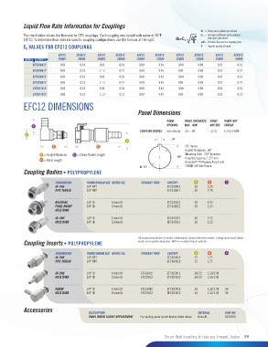
            EFC12 DIMENSIONS
                                                                Panel Dimensions

                                                                             PANEL    PANEL THICKNESS  PANEL    PANEL NUT
                D                                                            OPENING  MAX.–MIN.  NUT HEX  THREAD
                                                                 COUPLING BODIES  see drawing  .25 – .03  13/16  11/16-24UNF
             A
                                                                               .14"
                                                           A
                         B                   B                                        EFC Series
                                                                                      Gasket Thickness: .06"
                    A  = Height/Diameter  D  = Elbow Radial Length                    Mounting Hole: .720" diameter
                                                                                  .78"  Coupling Spacing: 1.25" min.
                    B  = Total Length
                                                                                      Greenlee  720 Keyway Punch and
                                                                                          ®
                                                                 Ø .72"               730BB-3/4 Hole Punch.
            Coupling Bodies • POLYPROPYLENE

                          TERMINATION    TUBING/THREAD SIZE  METRIC EQ.   STRAIGHT THRU   SHUTOFF   A  B  D
                          IN-LINE        1/4" NPT                            EFCD10412    .93   2.29
                          PIPE THREAD    3/8" NPT                            EFCD10612    .93   2.29

                          BULKHEAD       1/4" ID    6.4mm ID                 EFCD16412    .93   2.23
                          PANEL MOUNT    3/8" ID    9.5mm ID                 EFCD16612    .93   2.23
                          HOSE BARB

                          IN-LINE        1/4" ID    6.4mm ID                 EFCD17412    .93   2.23
                          HOSE BARB      3/8" ID    9.5mm ID                 EFCD17612    .93   2.23


                                                                All measurements are in inches (millimeters) unless otherwise noted. Tubing must meet stated
            Coupling Inserts • POLYPROPYLENE                    inside and outside diameters. MBLK = molded black material.


                          TERMINATION    TUBING/THREAD SIZE  METRIC EQ.   STRAIGHT THRU   SHUTOFF   A  B  D
                          IN-LINE        1/4" NPT                            EFCD24412    .72   1.77
                          PIPE THREAD    3/8" NPT                            EFCD24612    .72   1.77

                          IN-LINE        1/4" ID    6.4mm ID     EFC22412    EFCD22412    .60/.72   1.33/2.08
                          HOSE BARB      3/8" ID    9.5mm ID     EFC22612    EFCD22612    .60/.72   1.33/1.90


                          ELBOW          1/4" ID    6.4mm ID     EFC23412    EFCD23412    .63   1.32/1.45   .96
                          HOSE BARB      3/8" ID    9.5mm ID     EFC23612    EFCD23612    .63   1.32/1.45   .96


            Accessories                  DESCRIPTION                                       MATERIAL     PART NO.

                                         PANEL MOUNT GASKET REPLACEMENT  For sealing panel mount bodies listed above   Buna-N   1830300


                                                                            Smart fluid handling to take you forward, faster.  59
   55   56   57   58   59   60   61   62   63   64   65