
Page 335 - DESTACO Clamping Technologies
P. 335
technical appendix
Manual Clamping Technology
Calculating Exerting or Clamping Force
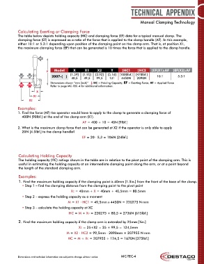
The table below depicts holding capacity (HC) and clamping force (EF) data for a typical manual clamp. The
clamping force (EF) is expressed as a ratio of the force that is applied to the clamp handle (AF). In this example,
either 10:1 or 5.3:1 depending upon position of the clamping point on the clamp arm. That is, at position X1,
the maximum clamping force (EF) that can be generated is 10 times the force that is applied to the clamp handle.
AF
Y Model X X1 X2 Y ‡HC1 ‡HC2 ‡EF(X1):AF ‡EF(X2):AF
[1.59] [1.95] [3.92] [5.16] [1000lbf.] [470lbf.]
EF EF 2007-( ) 40,5 49,5 99,5 131 4450N 2090N 10:1 5.3:1
Dimensions shown “mm [inch]” ‡ HC = Holding Capacity, EF = Exerting Force, AF = Applied Force
HC HC
2 1 Refer to page MC-TEC-4 for additional information.
X
X1
X2
Examples:
1. Find the force (AF) the operator would have to apply to the clamp to generate a clamping force of
400N [90lbf.] at the end of the clamp arm (X1).
AF = 400 ÷ 10 = 40N [9lbf.]
2. What is the maximum clamp force that can be generated at X2 if the operator is only able to apply
20N [4.5lbf.] to the clamp handle?
EF = 20 ∙ 5,3 = 106N [24lbf.]
Calculating Holding Capacity
The holding capacity (HC) ratings shown in the table are in relation to the pivot point of the clamping arm. This is
useful in estimating the holding capacity at an intermediate clamping point along the arm, or at a point beyond
the length of the standard clamping arm.
Examples:
1. Find the maximum holding capacity if the clamping point is 40mm [1.5in.] from the front of the base of the clamp.
• Step 1 – find the clamping distance from the clamping point to the pivot point
XC = 40mm + X = 40mm + 40,5mm = 80.5mm
• Step 2 – express the holding capacity as a moment
M = X1 ∙ HC1 = 49,5mm x 4450N = 220275 N∙mm
• Step 3 – calculate the holding capacity at XC
HC = M ÷ XC = 220275 ÷ 80,5 = 2736N [615lbf.]
2. Find the maximum holding capacity if the clamp arm is extended by 25mm [1in.]
XC = 25+X2 = 25 + 99,5 = 124,5mm
M = X2 ∙ HC2 = 99,5mm ∙ 2090mm = 207955 N∙mm
HC = M ÷ XC = 207955 ÷ 124,5 = 1670N [375lbf.]
Dimensions and technical information are subject to change without notice MC-TEC-4