
Page 338 - DESTACO Clamping Technologies
P. 338
technical appendix
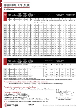
Specifications
Cylinder Cylinder Max.
Model Cylinder Rod Area Area Mechanical Distance From Pivot Holding Capacity Max Inlet Pressure Max. Clamping Force
no. Bore Diameter (Clamping (Opening Advantage at Max M.A* at 5 bar [72 psi]
Stroke) Stroke) (M.A.)
A B A B A B A B
(in) (mm) (in) (mm) (in2) (mm2) (in2) (mm2) A B
(in) (mm) (in) (mm) (lbf.) (N) (lbf.) (N) (PSIG) (bar) (PSIG) (bar) (lbf.) (N) (lbf.) (N)
Hold DownClamps
802-U 1.26 32 0.47 12 1.25 804 1.07 691 5.0 2.6 1.25 31.8 2.25 57.2 200 890 110 489 32 2.2 34 2.3 450 2010 234 1045
807-S 1.26 32 0.47 12 1.25 804 1.07 691 6.0 2.0 2.00 50.8 5.00 127.0 500 2220 260 1160 67 4.6 104 7.2 540 2412 180 804
807-U 1.26 32 0.47 12 1.25 804 1.07 691 6.4 3.3 2.00 50.8 3.75 95.3 375 1670 275 1220 47 3.2 67 4.6 576 2573 297 1327
810-S 1.57 40 0.63 16.0 1.95 1257 1.64 1056 5.0 2.9 2.38 60.5 5.31 134.9 750 3340 500 2220 77 5.3 89 6.1 702 3143 407 1823
810-U 1.57 40 0.63 16.0 1.95 1257 1.64 1056 6.1 2.9 2.38 60.3 4.88 123.8 600 2670 290 1290 50 3.5 51 3.5 856 3834 407 1823
812-U 0.75 19 0.25 6.4 0.4 258 0.39 253 4.3 2.9 1.25 31.8 2.25 57.2 100 440 55 245 53 3.6 43 3.0 136 613 92 413
846 1.57 40 0.63 16.0 1.95 1257 1.64 1056 5.6 3.5 2.25 57.2 3.25 82.6 750 3340 520 2310 69 4.7 76 5.3 786 3520 491 2200
847-S 2.05 50 0.63 16.0 3.29 2124 2.98 1923 4.0 1.8 3.25 82.6 6.50 165.1 1000 1118 650 2890 76 5.2 110 7.6 948 4248 426 1912
847-U 2.05 50 0.63 16.0 3.29 2124 2.98 1923 4.0 1.9 3.25 82.6 6.25 158.8 1000 4450 480 2135 76 5.2 77 5.3 948 4248 450 2018
858 2.48 63 0.98 25.0 4.83 3117 4.07 2626 4.4 2.3 3.00 76.2 7.00 177.8 4000 17800 2000 8900 145** 10.0** 145** 10.0** 1530 6857 800 3585
8021 1.26 32 0.47 12.0 1.07 691 1.25 8.4 2.2 1.3 1.70 43.2 2.60 66.0 390 1735 255 1135 145** 10.0** 145** 10.0•• 169 760 100 449
8071 1.57 40 0.63 16.0 1.64 1056 1.95 1257 4.2 2.4 2.25 57.2 3.25 82.6 450 2000 310 1380 65 4.5 79 5.4 496 2218 283 1267
8101 2.05 50 0.63 16.0 2.98 1923 3.29 2124 2.3 1.2 2.35 59.7 4.45 113.0 700 3110 370 1645 103 7.1 105 7.3 491 2202 253 1135
817-S 1.26 32 0.47 12.0 1.25 804 1.07 691 4 2.25 2.75 69.9 4.94 125.5 450 2000 200 890 90 6.2 64 4.4 360 1608 225 1005
817-U 1.26 32 0.47 12.0 1.25 804 1.07 691 4.1 2.5 2.75 69.9 5.00 127.0 375 1670 200 890 73 5.1 64 4.4 369 1648 225 1005
827-S 1.57 40 .063 16.0 1.95 1257 1.64 1056 3.5 2 2.50 63.5 5.30 134.6 700 3110 330 1470 103 7.1 85 5.8 491 2200 281 1257
827-U 1.57 40 0.63 16.0 1.95 1257 1.64 1026 3.5 2.2 2.13 54.1 3.25 82.6 600 2670 390 1735 88 6.1 91 6.3 491 2200 309 1383
868 2.48 63 0.98 25.0 4.83 3117 4.07 2626 4.9 2.3 5.00 127.0 8.25 209.6 4000 17800 2400 10675 145** 10.0** 145** 10.0** 1704 7637 800 3585
Cylinder Cylinder Max.
Model Cylinder Rod Area Area Mechanical Max Inlet Pressure
no. Bore Diameter (Clamping (Opening Advantage Holding Capacity at Max M.A
Stroke) Stroke) (M.A.)
(in) (mm) (in) (mm) (in2) (mm2) (in2) (mm2) (lbf.) (N) (PSIG) (bar)
Straight Line Action Clamps
803 1.26 32.0 0.47 12.0 1.25 804 1.07 691.2 7.5 600 2670 64 4.4 675 3015
816 0.75 19.1 0.25 6.4 0.44 285 0.39 253.4 7.7 100 400 30 2.0 244 1097
830 1.57 40.0 0.63 16.0 1.95 1257 1.64 1055.6 5.7 2500 11100 145** 10.0** 800 3582
850 2.05 52.0 0.63 16.0 3.29 2124 2.98 1922.7 5.2 16000 71200 145** 10.0** 1232 5522
8031 1.13 28.6 0.38 9.5 0.99 641 0.88 570.0 10.25 2000 890 145** 10.0** 731 3285
* Maximum cylinder pressure is 145 PSIG (10 bar). Never exceed this value
**Maximum inlet pressure in conjunction with maximum mechanical advantage does not exceed holding capacity. Do not exceed maximum cylinder pressure
Formula for calculating maximum allowable inlet pressure:
Maximum Line Pressure = Holding Capacity ÷ (Cylinder Area X Mechanical Advantage)
Formula for calculating max. exerting force:
Exerting Force = Inlet Pressure X Mechanical Advantage X Cylinder Area
B A
Example for Model 830
Holding Capacity = 11100N [2500lbf.]
Inlet Pressure 5bar (0,5 N/mm2) [72psig]
Cylinder Area = 1257mm2 [1.95in2] Spindle position to determine
Maximum Line Pressure = 11100 ÷ (1257 X 5.7) = 1,5 N/mm2 = 15bar mechanical advantage.
NOTE: This exceeds the maximum allowable cylinder pressure of 10bar
MC-TEC-7 Dimensions and technical information are subject to change without notice