
Page 13 - Apollo - Automatic Control Valves
P. 13
CONTROL VALVES
Dimensions
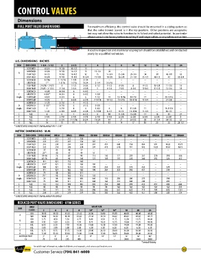
FULL PORT VALVE DIMENSIONS For maximum efficiency, the control valve should be mounted in a piping system so
that the valve bonnet (cover) is in the top position . Other positions are acceptable
but may not allow the valve to function to its fullest and safest potential . In particular
please consult the factory before installing 8” and larger valves, or any valves with a limit
switch, in positions other than described . Space should be taken into consideration
when mounting valves and their pilot systems .
A routine inspection and maintenance program should be established and conducted
yearly by a qualified technician .
U.S. DIMENSIONS - INCHES
DIM END CONN. 1-1/4 – 1-1/2 2 2-1/2 3 4 6 8 10 12 14 16 24
SCREWED 8-3/4 9-7/8 10-1/2 13 -- -- -- -- -- -- -- --
GROOVED 8-3/4 9-7/8 10-1/2 13 15-1/4 20 -- -- -- -- -- --
A
150# FLGD 8-1/2 9-3/8 10-1/2 12 15 17-3/4 25-3/8 29-3/4 34 39 40-3/8 62
300# FLGD 8-3/4 9-7/8 11-1/8 12-3/4 15-5/8 18-5/8 26-3/8 31-1/8 35-1/2 40-1/2 42 63-3/4
SCREWED 1-7/16 1 -11/16 1-7/8 2-1/4 -- -- -- -- -- -- -- --
GROOVED 1 * 1-3/16 1-7/16 1-3/4 2-1/4 3-5/16 -- -- -- -- -- --
B
150# FLGD 2-5/16 – 2-1/2 3 3-1/2 3-3/4 4-1/2 5-1/2 6-3/4 8 9-1/2 10-5/8 11-3/4 16
300# FLGD 2-5/8 – 3-1/16 3-1/4 3-3/4 4-1/8 5 6-1/4 7-1/2 8-3/4 10-1/4 11-1/2 12-3/4 18
SCREWED 4-3/8 4-3/4 6 6-1/2 -- -- -- -- -- -- -- --
C GROOVED 4-3/8 * 4-3/4 6 6-1/2 7-5/8 -- -- -- -- -- -- --
Angle 150# FLGD 4-1/4 4-3/4 6 6 7-1/2 10 12-11/16 14-7/8 17 -- 20-13/16 --
300# FLGD 4-3/8 5 6-3/8 6-3/8 7-13/16 10-1/2 13-3/16 15-9/16 17-3/4 -- 21-5/8 --
SCREWED 3-1/8 3-7/8 4 4-1/2 -- -- -- -- -- -- -- --
D GROOVED 3-1/8 * 3-7/8 4 4-1/2 5-5/8 -- -- -- -- -- -- --
Angle 150# FLGD 3 3-7/8 4 4 5-1/2 6 8 11-3/8 11 -- 15-11/16 --
300# FLGD 3-1/8 4-1/8 4-3/8 4-3/8 5-13/16 6-1/2 8-1/2 12-1/16 11-3/4 -- 16-1/2 --
E ALL 6 6 7 6-1/2 8 10 11-7/8 15-3/8 17 18 19 27
F ALL 3-7/8 3-7/8 3-7/8 3-7/8 3-7/8 3-7/8 6-3/8 6-3/8 6-3/8 6-3/8 6-3/8 8
G ALL 6 6-3/4 7-11/16 8-3/4 11-3/4 14 21 24-1/2 28 31-1/4 34-1/2 52
H ALL 10 11 11 11 12 13 14 17 18 20 20 28-1/2
* GROOVED END NOT AVAILABLE IN 1-1/4”
METRIC DIMENSIONS - M.M.
DIM END CONN. DN32-DN40 DN50 DN65 DN80 DN100 DN150 DN200 DN250 DN300 DN350 DN400 DN600
SCREWED 222 251 267 330 -- -- -- -- -- -- -- --
GROOVED 222 251 267 330 387 -- -- -- -- -- -- --
A
150# FLGD 216 238 267 305 381 451 645 756 864 991 1026 1575
300# FLGD 222 251 283 324 397 473 670 791 902 1029 1067 1619
SCREWED 37 43 48 57 -- -- -- -- -- -- -- --
GROOVED 25 * 30 37 44 57 -- -- -- -- -- -- --
B
150# FLGD 59-64 76 89 95 114 140 171 203 241 270 298 406
300# FLGD 67-78 83 95 105 127 159 191 222 260 292 324 457
SCREWED 111 121 152 165 -- -- -- -- -- -- -- --
C GROOVED 111* 121 152 165 194 -- -- -- -- -- -- --
Angle 150# FLGD 108 121 152 152 191 254 322 378 432 -- 529 --
300# FLGD 111 127 162 162 198 267 335 395 451 -- 549 --
SCREWED 79 98 102 114 -- -- -- -- -- -- -- --
D GROOVED 79 * 98 102 114 143 -- -- -- -- -- -- --
Angle 150# FLGD 76 98 102 102 140 152 203 289 279 -- 398 --
300# FLGD 79 105 111 111 148 165 216 306 298 -- 419 --
E ALL 152 152 178 165 203 254 302 391 432 457 483 686
F ALL 98 98 98 98 98 98 162 162 162 162 162 203
G ALL 152 171 195 222 298 356 533 622 711 794 876 1321
H ALL 254 279 279 279 305 330 356 432 457 508 508 724
* GROOVED END NOT AVAILABLE IN DN32
REDUCED PORT VALVE DIMENSIONS - A700 SERIES
ANSI VALVE SIZE
DIM
CLASS 3 4 6 8 10* 12* 16* 18 20 24
150 10.50 13.50 15.50 21.62 26.00 30.00 35.00 48.00 48.00 48.00
A
300 10.88 14.12 16.38 22.62 27.38 31.50 36.62 49.62 49.62 49.75
150 3.75 4.50 5.50 6.75 8.00 9.50 11.75 12.50 13.75 16.00
B
300 4.12 5.00 6.25 7.50 8.75 10.25 12.75 14.00 15.25 18.00
E ALL 6.00 6.50 7.92 10.00 11.88 15.38 17.00 19.00 19.00 19.00
F ALL 3.88 3.88 3.88 3.88 6.38 6.38 6.38 6.38 6.38 6.38
G ALL 6.75 8.75 11.75 14.00 21.00 24.50 28.00 34.50 34.50 34.50
H ALL 11.00 11.00 12.00 13.00 14.00 17.00 18.00 20.00 20.00 20.00
INTERIOR PORT 2” 3” 4” 6” 8” 10” 12” 16” 16” 16”
Cv 70 135 215 480 -- -- -- 3000 3300 3600
* consult factory
for additional information, submittal sheets and manuals, visit www.apollovalves.com
Customer Service (704) 841-6000 13