
Page 14 - Apollo - Automatic Control Valves
P. 14
CONTROL VALVES
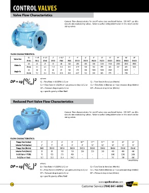
Valve Flow Characteristics
General flow characteristics for on/off valve sizes are listed below . DO NOT use this
data to size modulating valves . Refer to earlier sizing information in this brochure for
sizing valves .
FLOW CHARACTERISTICS:
US 1-1/4” 1-1/2” 2” 2-1/2” 3” 4” 6” 8” 10” 12” 14” 16” 24”
Valve Size
Metric DN32 DN40 DN50 DN65 DN80 DN100 DN150 DN200 DN250 DN300 DN350 DN400 DN600
US 23 27 47 68 120 200 450 760 1250 1940 2200 2850 6900
Globe Cv
Metric 5.5 6.5 11.3 16.3 28.7 47.9 108 182 299 465 527 683 1653
US 30 35 65 87 160 270 550 1000 1600 2400 -- 4000 --
Angle Cv
Metric 7.2 8.4 15.6 20.8 38.3 64.7 132 240 383 575 -- 958 --
DP = sg Q C ( ) 2 where: Q = Flow Rate in liters/sec (Metric)
Q = Flow Rate in USGPM (U .S .) or
v
Cv = Flow Rate in USGPM @ 1 psi pressure drop (U .S .) or
DP = Pressure drop in bar (Metric)
DP = Pressure drop in psi (U .S .) or Cv = Flow Rate in liter/sec @ 1 bar pressure drop (Metric)
sg = specific gravity of line fluid
Reduced Port Valve Flow Characteristics
General flow characteristics for on/off valve sizes are listed below . DO NOT use this
data to size modulating valves . Refer to earlier sizing information in this brochure for
sizing valves .
FLOW CHARACTERISTICS:
Flange Size (inches) 3” 4” 6” 8” 10” * 12” * 16” * 18” 20” 24”
Interior Port (inches) 2” 3” 4” 6” 8” 10” 12” 16” 16” 16”
Flange Size (Metric) DN80 DN100 DN150 DN200 DN250 DN300 DN400 DN450 DN500 DN600
Interior Port (Metric) 50 80 100 150 200 250 300 400 400 400
Cv (US Gal @ 1 PSID) 70 135 215 480 -- -- -- 3000 3300 3600
Cv (L/Sec @ 1 bar) 16.7 32.3 51.4 114.7 -- -- -- 717 789 860
* consult factory
DP = sg Q C ( ) 2 where: Q = Flow Rate in liters/sec (Metric)
Q = Flow Rate in USGPM (U .S .) or
v
Cv = Flow Rate in USGPM @ 1 psi pressure drop (U .S .) or
DP = Pressure drop in bar (Metric)
DP = Pressure drop in psi (U .S .) or Cv = Flow Rate in liter/sec @ 1 bar pressure drop (Metric)
sg = specific gravity of line fluid
www.apollovalves.com
14
Customer Service (704) 841-6000