
Page 4 - Apollo - Automatic Control Valves
P. 4
CONTROL VALVES
Pressure Reducing Valves
The APOLLO Basic Valve Model A65/A765 when fitted with an external control pilot circuit becomes a very effective pilot operated pressure reducing
valve . These “pilot operated regulators” reduce a higher inlet pressure to a constant outlet pressure over a wide range of demand without the pressure
“fall-off” characteristic of direct acting regulators . They offer a much higher flow capacity than “direct acting” types and are therefore sized differently; refer
to sizing guidelines . (Pages 6 and 7) They can provide additional hydraulic control functions, increasing the versatility of the valve . The Apollo series of
pressure reducing valves fall into three distinct types of applications, each of which is defined by their flow characteristics .
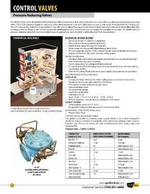
COMMERCIAL BUILDINGS A129/A729, A129LF/A729LF
• Valves are located in domestic supply lines
• Flow rates are driven by plumbing fixtures
• Demand may range from zero to moderate
• Water usage can vary greatly depending on time of day
• Piping is typically sized for 100% usage of fixtures that realistically never occurs
• Supply may be from city water pressure and/or pumps
SIZING GUIDELINES
• Minimum demand is a more important consideration than maximum demand!
• Line sized valves are rarely necessary
• Avoid sizing valves for anticipated future demand
• If more than one PRV is feeding the same zone, divide the total zone demand by
the number of PRV’s
• Refer to the Sizing Charts and contact your Apollo representative for assistance
RECOMMENDED APOLLO MODELS
A129 / A729
• 3-way pilot closes valve quickly when outlet pressure rises due to loss of flow
• Simple outlet pressure adjustable from 20-200 psi
• Pilot system strainer and isolation ball valves
• Manual air bleed valve
• Outlet pressure gauge
• Lead free construction
• Maintained inline
• Sizes: A129 – 1 ½”, 2”, 2 ½”, 3”, 4”, 6” A729 – 3”, 4”, 6”
• Refer to Materials / Specification for additional information
A129LF / A729LF
• Same features same a A129 / A729
• Equipped with bypass flow regulator for extreme low flows
* Image demonstrates fixture usage and is not a
recommendation for valve installation, sizing or building design. ADDITIONAL FUNCTIONS AVAILABLE
• Reverse flow check
FIXTURE USAGE REFERENCE TABLE
This guide is intended to illustrate water supply fixture units or flow demand of
plumbing fixtures, common in residential and commercial building water systems .
Consider that fixtures are never all used simultaneously when sizing your pilot
operated PRV .
1 Fixture Unit = 1 GPM / 3.79 l/m
FIXTURE TYPE WATER SUPPLY FIXTURE WATER AVERAGE
based on ½” size UNITS (WSFU) PER MINUTE USE (estimate)
Bath Tub – ¾” 4 gal 35 gal
Dishwasher-residential 1.5 gal 10-20 gal
Drinking fountain 0.5 Volume based on time
Hose bib 2.5 Volume based on time
Lavatory 2.2 gal 1-2 gal
Clinic sink 3 Volume based on time
Kitchen sink 1.5 Volume based on time
Mop basin 1.5 Volume based on time
Shower head 2.5 gal 25-50 gal
A129 Wash fountain- ¾” 4 Volume based on time
SHOWN WITH OPTIONAL Toilet-gravity tank 2.5 gal 3-7 gal
LOW FLOW BYPASS
(A129LF) Toilet-flushometer tank 1.6 Volume based on time
Washing Machine 18-40 gal / load
www.apollovalves.com
4
Customer Service (704) 841-6000