
Page 6 - Apollo - Automatic Control Valves
P. 6
CONTROL VALVES
Pressure Reducing Valve Sizing Guide
Sizing pilot operated reducing valves is not a complicated process . It starts with
determining requirements and following these guidelines in valve size selection .
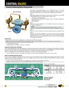
LOW FLOW BYPASS
Sizing the PRV involves two factors; Pressure Drop or Differential and Flow Rate .
STEP 1 –
Determine the application type where the valve is being used . Refer to the comments
“Sizing Guidelines” under the category selected on page 5 and 6 .
• Commercial / Residential Buildings –
• Refer to the fixture usage table for examples of usage in these types of applications .
• Distribution System
• Process System
STEP 2 –
Determine the pressure differential – this is the difference between the inlet pressure
(–) minus the outlet pressure .
Example:
INLET100 psi – OUTLET 50 psi (the pressure desired in the system) Difference = 50 psid
INLET 80 psi – OUTLET 40 psi (the pressure desired to provide to the system) Difference = 40 psid
STEP 3 –
A127LF Determine the flow rate (range) that your system may require, Minimum and Maximum flows .
STEP 4 –
Select the valve size from the table on the next page that best fits the application
conditions . Select the valve size that provides minimum and maximum flow ranges
(min .-max .) for the pressure drop/differential that was calculated . The following types
of PRV applications may apply .
SINGLE VALVE
One valve can handle the minimum and maximum at the pressure drop/differential required .
Example: INLET 100 psi with 50 psi OUTLET pressure (differential 50 psi), flows from 25 gpm to 500 gpm . Line size is 4” . Valve selection would be the reduced
port 4” . Outlet pressure would be constant 50 psi over the required flow range .
• 4” Full Port Valve 38-1000 gpm .
• 4” Reduced Port Valve (4” flanges x 3” internals) 29-630 gpm
SINGLE VALVE WITH LOW-FLOW BYPASS
Valves can be equipped with a direct acting regulator or low flow bypass to regulate extremely low flows . This bypass regulator, mounted on the larger
main valve, is set at a pressure of 5-10 psi higher than the main valve pilot . It reduces pressure under low flow conditions until the flow rate increases
beyond its capacity and the outlet pressure drops . When pressure reaches the main valve pilot setting, it opens to provide
pressure at the higher flows . The low-flow bypass configuration is typical for use in “building applications .”
• Direct acting low flow regulators have limited flow capacity . They are most effectively applied to valves sizes 6” x 4” and smaller .
PARALLEL PRESSURE REDUCING VALVES
If one (1) valve is capable of handling the low flow requirements but not the high flow, then two parallel valves may be required . Similar to the low
flow bypass, the smaller PRV controls the lower flow rates at a slightly higher pressure setting than the larger PRV . This PARALLEL configuration allows
pressure control over a wide range of flows .
• To avoid a gap in flow ranges, select valves so the smaller valve high flow overlaps the larger valve low flow .
Example: INLET 80 psi with 40 psi OUTLET pressure (differential 40 psi) Flows from 10 gpm to 800 gpm .
Selection options would be:
LOW FLOW
1 ½” flow range 5 gpm - 154 gpm
2” flow range 9 gpm - 260 gpm
HIGH FLOW
4” flow range 38 gpm - 1000 gpm
6”x 4” flow range 41 gpm - 1100 gpm
PARALLEL PRESSURE
REDUCING VALVE
APPLICATION
www.apollovalves.com
6
Customer Service (704) 841-6000