
Page 65 - Wieland - Safety: Safe system solutions for automation technology
P. 65
safe relay
Overview of devices | Part numbers
Type Rated voltage Terminals Part no. Std. Pack
SNE 1 24 V DC Screw terminals R1.188.3950.0 1
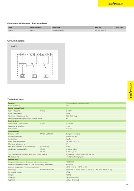
Circuit diagram
SNE 1
relay
safe
Technical data
Function Emergency stop expansion relay
Function display none
Power supply circuit
A1/A2 24 V DC
Rated voltage U N
Rated consumption 0.7 W
Operating voltage range U B 0.63 - 1.25 x U N
Electrical isolation supply circuit - control circuit yes
Control circuit
Input current / peak current A1/A2 ca. 29 mA
12 ms
Response time t A1 / t A2
Release time t R < 20 ms
Output circuit
Enabling paths 11/12/14, 21/22/24 changeover contact
Contact assignment forcebly guided
Contact type Ag-alloy
Rated switching voltage 230 V AC, 24 V DC
Max. thermal current I th 8 A
Max. total current I of all current path (Tu = 55 ºC) 72 A²
2
Application category (NO) AC-15 U e 230 V, I e 2 A
DC-13 U e 24 V, I e 3 A
Short-circuit protection (NO), lead fuse / circuit breaker 6 A class gL / melting integral < 100 A²s
6
Mechanical life 10 x 10 switching cycles
General data
Creepage distances and clearances between the circuits EN 61810-5
Protection degree according to EN 60529 (housing / terminals) IP20 / IP20
Ambient temperature / storage temperature -40 ºC - +70 ºC / -40 ºC - + 70
Wire range fine-stranded / solid 0.25 mm² – 4.0 mm² (AWG 24-12) / 0.25 – 6.0 mm (AWG 24-10)
2
Permissible torque 0.5 Nm
Weight 0.06 kg
Standards EN 50205 (Type B)
Approvals (pending)
cURus
65