Page 10 - Clippard - Miniature Pneumatic Products and Solutions
P. 10

STAINLESS STEEL CYLINDER


                                                                                   Stroke
              NUMBERING SYSTEM                                                     In inches & fractions of an inch


                   ❑          ❑         ❑          -        ❑         -        ❑          -       ❑


            Mounting Type            Rod Type               Bore                          Options
            S - Stud                 D - Double Ended Rod   5/32” - page 9                C -  Cushions
            U - Universal            R -  Rotating Rod      05 - 5/16”     17 - 1 1/16”   F -  Cushion Front End
            C - Clevis               N - Non-Rotating Rod   08 - 1/2”      20 - 1 1/4”    R -  Cushion Rear End
            F - Front Block          H - Hollow Rod         09 - 9/16”     24 - 1 1/2”    M - Magnetic Piston for Position
            E - End Stud   Cylinder Type                    10 - 5/8”      28 - 1 3/4”       Sensors
                                                                           32 - 2”
            T - Trunnion   D - Double Acting                12 - 3/4”      40 - 2 1/2”    B -  Bumpers
                           S - Single Acting                14 - 7/8”      48 - 3”        W - Rod Wiper
                           R - Reverse Acting                                             V -  FKM Seals
                                                                                          N - No Threads
                           F - Front Spring Bias                                          S -  Side Ported
                           B - Back Spring Bias
                                                                                          H - Heavy Spring
                                                                                          P* -  Rotated Ports
                                                                                RoHS         *  See page 4
            Not all combinations are available - consult factory                          TG -  PTFE Based Grease

              SPECIFICATIONS                    Bore Size
                                                  5/16”  1/2”  9/16”  5/8”    3/4”      7/8”  1-1/16”1-1/4” 1-1/2”  1-3/4”      2”      2-1/2”    3”
                                               Force Factor - Extend (Area)
                STAINLESS STEEL CYLINDER           0.07   0.19    0.25    0.31    0.44      0.60     0.88      1.2       1.7       2.4        3.1        4.9      7.0
              STANDARD & HEAVY SPRING FORCES
                                                Rod Size
                                                   1/8”   3/16”  3/16”  3/16”   1/4”      1/4”     5/16”    3/8”    7/16”     1/2”      5/8”       5/8”    3/4”
                                               Rod Area
                                                   0.01   0.03    0.03    0.03    0.05      0.05     0.08     0.11     0.15     0.20      0.31      0.31    0.44
                                               Force Factor - Retract (Area)
                                                   0.06   0.16    0.22    0.28    0.39      0.55     0.80     1.09     1.55     2.20      2.90      4.59    6.56

              lbs.
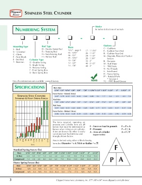
                                              The force required, operating air
                                              pressure and cylinder bore are all
                                 5/16   5/16   factors that must be determined or  F - Force or load in pounds       F = P x A
                                              known when sizing an air cylinder.
                                              If two are known the other is easily  P - Pressure                               P = F / A
                                                                              A - Area of cylinder                  A = F / P
                                              calculated per the formulas and    (square inches)
                                              triangle shown below.
                5/16  1/2  9/16  5/8  3/4  7/8  1 1/16  1 1/4  1 1/2  1 3/4  2  2 1/2  Area is derived using either of the following
                                              formulas: Diameter  x 0.7854 or Radius  x π
                            bore                               2                 2
                                                                                                    F
             Standard Spring Forces (lbs)
                    Bore         5/16”  1/2”  9/16”  5/8”    3/4”    7/8”  1-1/16” 1-1/4”  1-1/2”   1-3/4”      2”      2-1/2”
                  At Rest         0.5      0.9     1.7      1.3      3.0      3.0       2.0        4.5        4.5       11.0      15.0      15.0
                                                                                                P A
              Compressed     1.0      2.0     4.0      4.0      6.0      6.0       7.0       10.0      10.0      24.0      30.0      30.0
             Heavy Spring Forces (lbs)
                  Bore            5/16”  1/2”  9/16”  5/8”    3/4”    7/8”  1-1/16” 1-1/4”  1-1/2”   1-3/4”      2”  2-1/2”
                At Rest            N/A     2.0     N/A     3.3      5.0      5.0       5.5        8.5        8.5       N/A       N/A  N/A
             Compressed      N/A     4.0     N/A     9.0     10.0    10.0     13.0      17.0      17.0      N/A       N/A  N/A

         3                                       Clippard Instrument Laboratory, Inc. 877-245-6247 www.clippard.com/cylinders/
   5   6   7   8   9   10   11   12   13   14   15