
Page 113 - Parker - Heavy Duty Hydraulic Cylinders
P. 113
Catalog HY08-1114-4/NA Heavy Duty Hydraulic Cylinders
Ports Series 2H / 3H Engineering Data
Ports Table B
Series 2H and 3H cylinders can be supplied with SAE straight SAE Straight Thread O-Ring Ports
O-ring ports or NPTF pipe thread ports. If specified on your Size Tube Thread Size Tube Thread
order, extra ports can be provided on the sides of heads or
caps that are not occupied by mountings or cushion valve. No. O.D. (In.) Size No. O.D. (In.) Size
Standard port location is position 1 as shown on line 2 3 0.13 5/16 - 24 12 0.75 1 1/16 - 12
—
—
0.19
3/8 - 24
—
drawings in product catalog and Figure 1 below. Cushion
adjustment needle and check valves are at positions 2 and 4 0.25 7/16 - 20 16 1.00 1 5/16 - 12
4 (or 3), depending on mounting style. Heads or caps 5 0.31 1/2 - 20 20 1.25 1 5/8 - 12
which do not have an integral mounting can be rotated and 6 0.38 9/16 - 18 24 1.50 1 7/8 - 12
assembled with ports at 90° or 180° from standard position. 8 0.50 3/4 - 16 32 2.00 2 1/2 - 12
Mounting styles on which head or cap can be rotated at 10 0.63 7/8 - 14 — — —
no extra charge are shown in Table A below. To order, Note: For the pressure ratings of individual connectors,
specify by position number. In such assemblies the cushion contact your connector supplier. Hydraulic cylinders applied
adjustment needle and check valve rotate accordingly since with meter out or deceleration circuits are subject to intensified
their relationship with port position does not change. pressure at the cylinder piston rod end. The rod end pressure
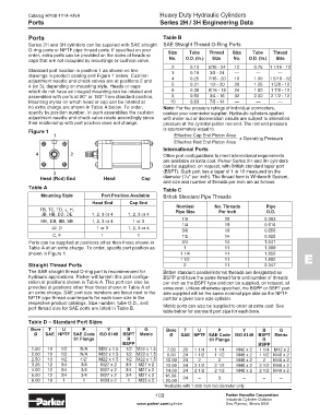
Figure 1 is approximately equal to:
1 Effective Cap End Piston Area x Operating Pressure
Effective Rod End Piston Area
International Ports
4 2 Other port configurations to meet international requirements
are available at extra cost. Parker Series 2H and 3H cylinders
can be supplied, on request, with British standard taper port
3 (BSPT). Such port has a taper of 1 in 16 measured on the
1
Head (Rod) End Head Cap diameter ( /16" per inch). The thread form is Whitworth System,
and size and number of threads per inch are as follows:
Table A Table C
Mounting Style Port Position Available British Standard Pipe Threads
Head End Cap End
Nominal
TB, TC, TD, J, H, Pipe Size No. Threads Pipe
Per Inch
O.D.
JB, HB, DD, DE 1, 2, 3 or 4 1, 2, 3 or 4
HH, DB, BB, SB 1, 2, 3 or 4 1 or 3 1/8 28 0.383
JJ, D 1 or 3 1, 2, 3 or 4 1/4 19 0.518
0.656
3/8
19
C, F 1 1 1/2 14 0.825
Ports can be supplied at positions other than those shown in 3/4 14 1.041
Table A at an extra charge. To order, specify port position as 1 11 1.309
shown in Figure 1. 1 1/4 11 1.650
1 1/2 11 1.882 E
Straight Thread Ports 2 11 2.347
The SAE straight thread O-ring port is recommended for British standard parallel internal threads are designated as
hydraulic applications. Parker will furnish this port configu- BSPP and have the same thread form and number of threads
ration at positions shown in Table A. This port can also be per inch as the BSPT type and can be supplied, on request, at
provided at positions other than those shown in Table A at extra cost. Unless otherwise specified, the BSPP or BSPT port
an extra charge. SAE port size numbers are listed next to the size supplied will be the same nominal pipe size as the NPTF
NPTF pipe thread counterparts for each bore size in the port for a given bore size cylinder.
respective product catalogs. Size number, tube O.D., and Metric ports can also be supplied to order at extra cost. See
port thread size for SAE ports are listed in Table B.
table below for standard port size for each bore.
Table D – Standard Port Sizes
Bore T U P Y B G Bore T U P Y B G
Ø SAE NPTF SAE Code ISO 6149 BSPT Metric Ø SAE NPTF SAE Code ISO 6149 BSPT Metric
61 Flange R 61 Flange R
BSPP BSPP
1.50 10 1/2 N/A M22 x 1.5 1/2 M22 x 1.5 7.00 20 1 1/4 1 1/4 M42 x 2 1 1/4 M42 x 2
2.00 10 1/2 N/A M22 x 1.5 1/2 M22 x 1.5 8.00 24 1 1/2 1 1/2 M48 x 2 1 1/2 M48 x 2
2.50 10 1/2 1/2 M22 x 1.5 1/2 M22 x 1.5 10.00 24 2 2 M48 x 2 2 M48 x 2
1
3.25 12 3/4 3/4 M27 x 2 3/4 M27 x 2 12.00 24 2 1/2 2 1/2 M48 x 2 2 1/2 M48 x 2
4.00 12 3/4 3/4 M27 x 2 3/4 M27 x 2 14.00 24 2 1/2 2 1/2 M48 x 2 2 1/2 M48 x 2
5.00 12 3/4 3/4 M27 x 2 3/4 M27 x 2 16.00- 24 – 3 – – –
6.00 16 1 1 M33 x 2 1 M33 x 2 20.00
1 Available with 1.000 inch rod diameter only.
103 Parker Hannifin Corporation
Industrial Cylinder Division
www.parker.com/cylinder Des Plaines, Illinois USA