
Page 115 - Parker - Heavy Duty Hydraulic Cylinders
P. 115
Catalog HY08-1114-4/NA Heavy Duty Hydraulic Cylinders
Stroke Data / Mounting Groups Series 2H / 3H Engineering Data
Stroke Data -.015" up to 20" stroke, +.031" to -.020" for 21" to 60"
Parker cylinders are available in any practical stroke and +.031" to -.031" for greater than 60" stroke. For
length. The following information should prove helpful closer tolerances on stroke length, it is necessary to
to you in selecting the proper stroke for your cylinder specify the required tolerance plus the pressure and
application. temperature at which the cylinder will operate. Stroke
tolerances smaller than .015" are not generally practical
Stroke Tolerances due to elasticity of cylinders. If machine design requires
Stroke length tolerances are required due to buildup such close tolerances, use of a stroke adjuster may
of tolerances of piston, head, cap and cylinder tube. achieve the desire result.
Standard production of stroke tolerances run +.031" to
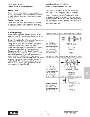
Mounting Groups Group 1 FIXED MOUNTS which absorb force on cylinder centerline.
Standard mountings for fluid power cylinders fall into
three basic groups. The groups can be summarized as
follows:
Group 1 Straight Line Force Transfer with fixed mounts
which absorb force on cylinder centerline. Heavy-Duty Service
Group 2 Pivot Force Transfer. Pivot mountings permit a For Thrust Loads Styles HB, HH, TC
cylinder to change its alignment in one plane. For Tension Loads Styles JB, JJ, TB
Group 3 Straight Line Force Transfer with fixed mounts Medium-Duty Service Styles H, HB
For Thrust Loads
which do not absorb force on cylinder centerline. For Tension Loads Styles J, JB
Because a cylinder’s mounting directly affects the Light-Duty Service
maximum pressure at which the cylinder can be used, For Thrust Loads Style H
the chart below should be helpful in selection of the For Tension Loads Style J
proper mounting combination for your application. Group 2 PIVOT MOUNTS which absorb force on cylinder centerline.
Stroke length, piston rod connection to load, extra piston
rod length over standard, etc., should be considered
for thrust loads. Alloy steel mounting bolts are recom-
mended for all mounting styles, and thrust keys are
recommended for Styles C and F.
Heavy-Duty Service
For Thrust Loads Styles DD, D, DE
For Tension Loads Styles BB, DD, D, DB, DE
Medium-Duty Service
For Thrust Loads Styles BB, SB E
For Tension Loads Styles BB, SB
Group 3 FIXED MOUNTS which do not absorb force on the centerline.
Heavy-Duty Service
For Thrust Loads Styles C, CP
For Tension Loads Styles C, CP
Medium-Duty Service
For Thrust Loads Styles F, FP
For Tension Loads Styles F, FP
105 Parker Hannifin Corporation
Industrial Cylinder Division
www.parker.com/cylinder Des Plaines, Illinois USA