
Page 120 - Parker - Heavy Duty Hydraulic Cylinders
P. 120
Catalog HY08-1114-4/NA Heavy Duty Hydraulic Cylinders
Cushioning Series 2H / 3H Engineering Data
An Introduction to Cushioning Formula
Cushioning is recommended as a means of controlling the Cushioning calculations are based on the formula E=(1/2)
deceleration of masses, or for applications where piston mv for horizontal applications. For inclined or vertically
2
speed is in excess of 4 in/sec and the piston will make downward or upward applications, this is modified to:
full stroke. Cushioning extends cylinder life and reduces E = (1/2)mv + mg(L/12) x sin(a)
2
undesirable noise and hydraulic shock. Built-in “cushions” (for inclined or vertically downward direction of mass)
are optional and can be supplied at the head and cap ends
of a cylinder without affecting its envelope or mounting E = (1/2)mv – mg(L/12) x sin(a)
2
dimensions. (for inclined vertically upward direction of mass)
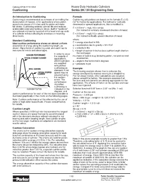
Standard Cushioning where:
Ideal cushion performance shows an almost uniform E = energy absorbed in ft-lb
absorption of energy along the cushioning length, as g = acceleration due to gravity = 32.2 ft/s 2
shown. Many forms of cushioning exist, and each has its v = velocity in ft/s
own specific merits and advantages. L = length of cushion in inches (see cushion length chart on
In order to cover the next page).
the majority of m = mass of load in slug (including piston, rod and rod end
applications, accessories.
2H/3H cylinders a = angle to the horizontal in degrees
are supplied p = pressure in psi
with profiled
cushioning as Example:
standard. Final The following example shows how to calculate the
speed may be energy developed by masses moving in a straight line.
adjusted using For non-linear motion, other calculations are required;
the cushion please consult the factory. The example assumes that
screw. The the bore and rod diameter are already appropriate for the
performance application. The effects of friction on the cylinder and load
of profiled have been ignored.
cushioning is
indicated on the Selected bore/rod 6.00" bore x 2.50" rod (No. 1 rod)
diagram, and Cushion at the cap end.
cushion performance for each of the rod sizes available is Pressure = 2,500 psi
illustrated graphically in the charts on the following pages.
Mass = 685 slugs = weight in lb / (32.2 ft/s )
2
Note: Cushion performance will be affected by the use of Velocity = 1.3 ft/s
water or high water based fluids. Please consult factory
for details. Cushion length = 1.313 inch
a = 45°
Cushion Length Sin (a) = 0.70
Where specified, 2H/3H cylinder incorporates the longest E = (1/2)mv2 + mgl/12 x Sin (a)
cushion sleeve and spear that can be accommodated = (1/2) x 685 x 1.3 + 685 x 32.2 x 1.313/12 x 0.70
2
within the standard envelope without reducing the rod = 2,268 ft-lb
bearing and piston bearing length. See cushion lengths
on the next page. Cushions are adjustable via recessed
needle valves.
Cushion Calculation
The charts on the cushion energy absorption capacity
data page show the energy absorption capacity for each a
bore/rod combination at the head (annulus) and the cap
(full bore) ends of cylinder. The charts are valid for piston Note: In the above example velocity is greater than 1 ft/s
velocities within a range of 0.33 to 1 ft/s. For velocities Therefore, a de-rating factor of 0.75 must be applied to
between 1ft/s and 1.64 ft/s the energy values derived from the calculated value of E. Applying this correction factor
the charts should be reduced by 25%. For velocities less will increase the energy value to 3024 ft-lb (2268/0.75 =
than 0.33 ft/s where large masses are involved, and for 3024 ft-lb). A review of the graph for the cap end cushion
velocities greater than 1.60 ft/s, a special cushion profile of a 6 inch bore x 2.50" rod cylinder operating at 2500 psi
may be required. Please consult the factory for details. indicates that it can absorb approximately 3200 ft-lb
The cushion capacity of the head end is less than the cap, maximum of energy. Since 3024 ft-lb is less than the
and reduces to zero at high drive pressures due to the maximum allowable of 3200 ft-lb, the cylinder can be
pressure intensification effect across the piston. applied as indicated. If the calculated energy exceeds the
value shown on the curve, select a larger bore cylinder
The energy absorption capacity of the cushion decreases and/or reduce the operating pressure and recalculate the
with drive pressure. energy. Compare the newly calculated energy value to
the appropriate curve to ensure it does not exceed the
maximum allowable energy.
110 Parker Hannifin Corporation
Industrial Cylinder Division
www.parker.com/cylinder Des Plaines, Illinois USA