
Page 28 - Parker - Heavy Duty Hydraulic Cylinders
P. 28
Catalog HY08-1114-4/NA Heavy Duty Hydraulic Cylinders
Mounting Information – 1.50" to 6.00" Bore Series 2H
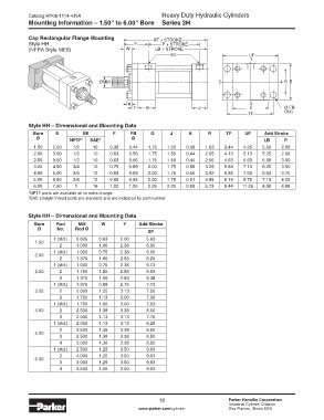
Cap Rectangular Flange Mounting XF + STROKE
Style HH Y P + STROKE
(NFPA Style ME6) W LB + STROKE
EE UF
1
ØMM 2 4 R E
K 3
F G J E Ø FB
TF (X4)
Style HH – Dimensional and Mounting Data
Bore E EE F FB G J K R TF UF Add Stroke
Ø NPTF 1 SAE 2 Ø LB P
1.50 2.50 1/2 10 0.38 0.44 1.75 1.50 0.38 1.63 3.44 4.25 5.00 2.88
2.00 3.00 1/2 10 0.63 0.56 1.75 1.50 0.44 2.05 4.13 5.13 5.25 2.88
2.50 3.50 1/2 10 0.63 0.56 1.75 1.50 0.44 2.55 4.63 5.63 5.38 3.00
3.25 4.50 3/4 12 0.75 0.69 2.00 1.75 0.56 3.25 5.88 7.13 6.25 3.50
4.00 5.00 3/4 12 0.88 0.69 2.00 1.75 0.56 3.82 6.38 7.63 6.63 3.75
5.00 6.50 3/4 12 0.88 0.94 2.00 1.75 0.81 4.95 8.19 9.75 7.13 4.25
6.00 7.50 1 16 1.00 1.06 2.25 2.25 0.88 5.73 9.44 11.25 8.38 4.88
1 NPTF ports are available at no extra charge.
2 SAE straight thread ports are standard and are indicated by port number.
Style HH – Dimensional and Mounting Data
Bore Rod MM W Y Add Stroke
Ø No. Rod Ø
XF
1 (std.) 0.625 0.63 2.00 5.63
1.50
2 1.000 1.00 2.38 6.00
1 (std.) 1.000 0.75 2.38 6.00
2.00
2 1.375 1.00 2.63 6.25
1 (std.) 1.000 0.75 2.38 6.13
2.50 2 1.750 1.25 2.88 6.63
3 1.375 1.00 2.63 6.38
1 (std.) 1.375 0.88 2.75 7.13
3.25 2 2.000 1.25 3.13 7.50
3 1.750 1.13 3.00 7.38
1 (std.) 1.750 1.00 3.00 7.63
4.00 2 2.500 1.38 3.38 8.00
3 2.000 1.13 3.13 7.75
1 (std.) 2.000 1.13 3.13 8.25
2 3.500 1.38 3.38 8.50
5.00
3 2.500 1.38 3.38 8.50
4 3.000 1.38 3.38 8.50
1 (std.) 2.500 1.25 3.50 9.63
2 4.000 1.25 3.50 9.63
6.00
3 3.000 1.25 3.50 9.63
4 3.500 1.25 3.50 9.63
18 Parker Hannifin Corporation
Industrial Cylinder Division
www.parker.com/cylinder Des Plaines, Illinois USA