
Page 31 - Parker - Heavy Duty Hydraulic Cylinders
P. 31
Catalog HY08-1114-4/NA Heavy Duty Hydraulic Cylinders
Mounting Information – 1.50" to 6.00" Bore Series 2H
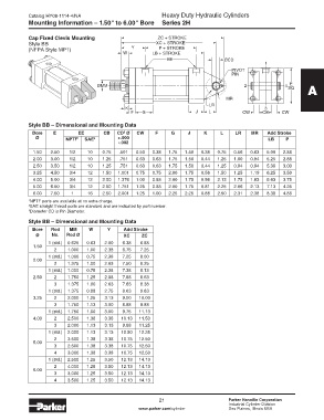
Cap Fixed Clevis Mounting ZC + STROKE
Style BB XC + STROKE
(NFPA Style MP1) Y P + STROKE
W LB + STROKE
EE ØCD
1
PIVOT
PIN
E
ØMM 2 4 SQ A
MR
LR
K 3
F G J L CW CB CW
Style BB – Dimensional and Mounting Data
Bore E EE CB CD Ø CW F G J K L LR MR Add Stroke
3
Ø NPTF 1 SAE 2 +.000 LB P
-.002
1.50 2.50 1/2 10 0.75 .501 0.50 0.38 1.75 1.50 0.38 0.75 0.56 0.63 5.00 2.88
2.00 3.00 1/2 10 1.25 .751 0.63 0.63 1.75 1.50 0.44 1.25 1.00 0.94 5.25 2.88
2.50 3.50 1/2 10 1.25 .751 0.63 0.63 1.75 1.50 0.44 1.25 0.94 0.94 5.38 3.00
3.25 4.50 3/4 12 1.50 1.001 0.75 0.75 2.00 1.75 0.56 1.50 1.25 1.19 6.25 3.50
4.00 5.00 3/4 12 2.00 1.376 1.00 0.88 2.00 1.75 0.56 2.13 1.75 1.63 6.63 3.75
5.00 6.50 3/4 12 2.50 1.751 1.25 0.88 2.00 1.75 0.81 2.25 2.06 2.13 7.13 4.25
6.00 7.50 1 16 2.50 2.001 1.25 1.00 2.25 2.25 0.88 2.50 2.31 2.38 8.38 4.88
1 NPTF ports are available at no extra charge.
2 SAE straight thread ports are standard and are indicated by port number.
3 Diameter CD is Pin Diameter.
Style BB – Dimensional and Mounting Data
Bore Rod MM W Y Add Stroke
Ø No. Rod Ø XC ZC
1 (std.) 0.625 0.63 2.00 6.38 6.88
1.50
2 1.000 1.00 2.38 6.75 7.25
1 (std.) 1.000 0.75 2.38 7.25 8.00
2.00
2 1.375 1.00 2.63 7.50 8.25
1 (std.) 1.000 0.75 2.38 7.38 8.13
2.50 2 1.750 1.25 2.88 7.88 8.63
3 1.375 1.00 2.63 7.63 8.38
1 (std.) 1.375 0.88 2.75 8.63 9.63
3.25 2 2.000 1.25 3.13 9.00 10.00
3 1.750 1.13 3.00 8.88 9.88
1 (std.) 1.750 1.00 3.00 9.75 11.13
4.00 2 2.500 1.38 3.38 10.13 11.50
3 2.000 1.13 3.13 9.88 11.25
1 (std.) 2.000 1.13 3.13 10.50 12.25
2 3.500 1.38 3.38 10.75 12.50
5.00
3 2.500 1.38 3.38 10.75 12.50
4 3.000 1.38 3.38 10.75 12.50
1 (std.) 2.500 1.25 3.50 12.13 14.13
2 4.000 1.25 3.50 12.13 14.13
6.00
3 3.000 1.25 3.50 12.13 14.13
4 3.500 1.25 3.50 12.13 14.13
21 Parker Hannifin Corporation
Industrial Cylinder Division
www.parker.com/cylinder Des Plaines, Illinois USA