Page 59 - Parker - Heavy Duty Hydraulic Cylinders
P. 59

Catalog HY08-1114-4/NA                            Heavy Duty Hydraulic Cylinders
            Mounting Information – 7.00" and 8.00" Bore       Series 3H


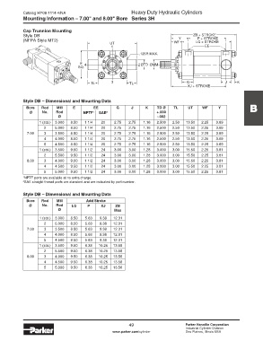
            Cap Trunnion Mounting
            Style DB                                                                       ZB + STROKE
                                                                                             P + STROKE
            (NFPA Style MT2)                                                        Y       LG + STROKE
                                                    UT                            WF
                                                     1                                          EE
                                                                  .125R MAX.

                                      E  4                       2 ØTD ØMM
                                     SQ.


                                           TL        3       TL                         G                 J    K
                                                                                        XJ + STROKE

            Style DB – Dimensional and Mounting Data

             Bore   Rod    MM      E         EE        G      J      K    TD Ø    TL     UT    WF      Y             B
               Ø     No.   Rod          NPTF 1  SAE 2                     +.000
                            Ø                                             -.002
                   1 (std.)  3.000  8.50  1 1/4  20   2.75   2.75   1.16  2.500  2.50   13.50  2.25   3.69
                      2    5.000  8.50  1 1/4   20    2.75   2.75   1.16  2.500  2.50   13.50  2.25   3.69
              7.00    3    3.500  8.50  1 1/4   20    2.75   2.75   1.16  2.500  2.50   13.50  2.25   3.69
                      4    4.000  8.50  1 1/4   20    2.75   2.75   1.16  2.500  2.50   13.50  2.25   3.69
                      5    4.500  8.50  1 1/4   20    2.75   2.75   1.16  2.500  2.50   13.50  2.25   3.69
                   1 (std.)  3.500  9.50  1 1/2  24   3.00   3.00   1.28  3.000  3.00   15.50  2.25   3.81
                      2    5.500  9.50  1 1/2   24    3.00   3.00   1.28  3.000  3.00   15.50  2.25   3.81
              8.00    3    4.000  9.50  1 1/2   24    3.00   3.00   1.28  3.000  3.00   15.50  2.25   3.81
                      4    4.500  9.50  1 1/2   24    3.00   3.00   1.28  3.000  3.00   15.50  2.25   3.81
                      5    5.000  9.50  1 1/2   24    3.00   3.00   1.28  3.000  3.00   15.50  2.25   3.81
            1 NPTF ports are available at no extra charge.
            2 SAE straight thread ports are standard and are indicated by port number.


            Style DB – Dimensional and Mounting Data
             Bore         Rod   MM       Add Stroke
               Ø     No.   Rod    LG      P     XJ     ZB
                            Ø                         Max

                   1 (std.)  3.000  8.50  5.63  9.38  12.31
                      2    5.000  8.50   5.63  9.38   12.31
              7.00    3    3.500  8.50   5.63  9.38   12.31
                      4    4.000  8.50   5.63  9.38   12.31
                      5    4.500  8.50   5.63  9.38   12.31
                   1 (std.)  3.500  9.50  6.38  10.25  13.56
                      2    5.500  9.50   6.38  10.25  13.56
              8.00    3    4.000  9.50   6.38  10.25  13.56
                      4    4.500  9.50   6.38  10.25  13.56
                      5    5.000  9.50   6.38  10.25  13.56


                                                             49                        Parker Hannifin Corporation
                                                                                       Industrial Cylinder Division
                                                     www.parker.com/cylinder           Des Plaines, Illinois USA
   54   55   56   57   58   59   60   61   62   63   64