Page 63 - Parker - Heavy Duty Hydraulic Cylinders
P. 63

Catalog HY08-1114-4/NA                            Heavy Duty Hydraulic Cylinders
            Mounting Information – Large Bore                 Series 3H


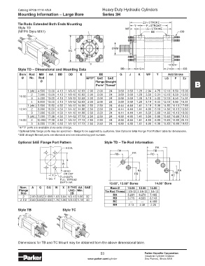
            Tie Rods Extended Both Ends Mounting                                 Y    Z J  + STROKE
            Style TD                                                        WF          L P G +STROKE
                                                                                          + STROKE
            (NFPA Style MX1)                         1                                     E E               D D


                                           E                   2    Ø M M
                                          SQ.  4

                                                   A A
                                                       3                                                K
            Style TD – Dimensional and Mounting Data                     B B        G                J         B B
             Bore  Rod    MM   AA   BB    DD     E          EE           G    J     K   WF     Y     Add Stroke
              Ø    No.  Rod                          NPTF 1  SAE   SAE                             LG    P    ZJ
                         Ø                                Flange Straight
                                                          Ports   Thread 3                                           B
                                                               2
                 1 (std.) 4.500 13.00 4.13 1 1/8-12 12.63 2.00  2.00  24  3.69  3.69  1.28  2.94  4.75 12.13 8.50 15.06
                    2   7.000 13.00 4.13 1 1/8-12 12.63 2.00  2.00  24  3.69  3.69  1.28  3.50  5.31 12.13 8.50 15.63
            10.00
                    3   5.000 13.00 4.13 1 1/8-12 12.63 2.00  2.00  24  3.69  3.69  1.28  3.19  5.00 12.13 8.50 15.31
                    4   5.500 13.00 4.13 1 1/8-12 12.63 2.00  2.00  24  3.69  3.69  1.28  3.19  5.00 12.13 8.50 15.31
                 1 (std.) 5.500 15.50 4.50 1 1/4-12 14.88 2.50  2.50  24  4.44  4.44  1.41  3.19  5.38 14.50 10.13 17.69
            12.00   2   8.000 15.50 4.50 1 1/4-12 14.88 2.50  2.50  24  4.44  4.44  1.41  4.00  6.19 14.50 10.13 18.50
                    3   7.000 15.50 4.50 1 1/4-12 14.88 2.50  2.50  24  4.44  4.44  1.41  3.50  5.69 14.50 10.13 18.00
                 1 (std.) 7.000 17.38 4.50 1 1/4-12 17.13 2.50  2.50  24  4.88  4.88  1.41  3.50  5.88 15.63 10.88 19.13
            14.00   2  10.000 17.38 4.50 1 1/4-12 17.13 2.50  2.50  24  4.88  4.88  1.41  4.50  6.88 15.63 10.88 20.13
                    3   8.000 17.38 4.50 1 1/4-12 17.13 2.50  2.50  24  4.88  4.88  1.41  4.00  6.38 15.63 10.88 19.63
            1  NPTF ports are available at no extra charge.
            2  Optional SAE flange ports may be specified – flange to be supplied by customer. See Optional SAE Flange Port Pattern table for dimensions.
            3  SAE straight thread ports are standard and are indicated by port number.
            Optional SAE Flange Port Pattern                   Style TD – Tie Rod Information
                                        A DIA.                                                RA
                                                                       RA                    RB
                                                                      RB        RR         RC
                                         Q
                                      W

                                       HEAD                                        RA                      RA
                                       OR CAP                                    RB                      RB
                                X                                                                      RC
                              GG     Z-4 HOLES
                                     FULL THREAD
                                     DEPTH AA                     10.00", 12.00" Bores       14.00" Bore
             Nom.   A   Q    GG   W   X  Z-THD  AA  SAE            Bore Ø    10.00  12.00  14.00
            Flange                        UNC-  Min.            Tie Rod Thread 1 1/8-12 1 1/4-12 1 1/4-12
             Size                          2B                        RA      5.291  6.270  7.485
               2   2.00 3.062 1.688 1.53 0.84 1/2-13  1.06  32
             2 1/2  2.50 3.500 2.000 1.75 1.00 1/2-13  1.19  40      RB      3.775  4.555  6.143
                                                                     RC        —     —     4.409
                                                                     RR       2.13  2.38   2.25
            Style TB                  Style TC


            Dimensions for TB and TC Mount may be obtained from the above dimensional table.


                                                             53                        Parker Hannifin Corporation
                                                                                       Industrial Cylinder Division
                                                     www.parker.com/cylinder           Des Plaines, Illinois USA
   58   59   60   61   62   63   64   65   66   67   68